05 · Joints and actuators
| Part | 1 · Simulation |
| Run type | CPU · Mac or Colab CPU |
| Prerequisites | 01, 02 |
| Learn first | Calculus for Machine Learning |
| Time | ~45 min |
| Code | experiments/05-joints-and-actuators/experiment.py |
| Status | ✅ done |
Act on this lesson
Tick each step when you have done it. Saved in this browser only.
A
<position>actuator is a PD controller living inside the physics step: its gain sets the sag, and the armature decides whether the step can integrate it.
The problem
Section titled “The problem”The Menagerie SO-101 gives every joint the same servo: <position kp="998.22" kv="2.731" forcerange="-2.94 2.94"/> on a joint with armature="0.028", and a comment says these gains are not a one-to-one copy of the real servo’s (so101.xml). Why is kp almost 1000, what does armature do on a hobby servo, and what happens if you copy the gains but drop the armature? This lesson builds one gravity-loaded link, measures how kp sets sag and rise time, and finds where the same gains make the simulation diverge.
Before you read · 2 questions. Guess first; the lesson tells you why.
1. A <position> servo holds a link against gravity. You raise kp from 10 to 100. What happens to the sag and the rise time?
- The sag drops to zero; the rise time stays the same.
- Both fall ten times.
- The sag falls about ten times, the rise time only by about .
Why: Sag and rise time . In the kp sweep the sag goes 1.685° → 0.169° and the rise time 185.6 → 56.7 ms.
2. The SO-101 model adds armature="0.028" to every joint. In a real geared servo, what does armature stand for?
- The friction in the gearbox.
- The spinning motor rotor, which the gearbox makes feel much heavier at the joint (rotor inertia × gear ratio²).
- The mass of the servo’s plastic case.
Why: Armature adds to the joint’s diagonal of the mass matrix; for a geared motor it is the reflected rotor inertia (In plain words, Math details). Numerically it lowers .
Core idea
Section titled “Core idea”In plain words
Section titled “In plain words”A <position> actuator behaves like a spring plus a shock absorber pulling the joint toward the commanded angle. The spring’s stiffness is kp: the further from the target, the harder it pulls. The shock absorber’s strength is kv: the faster the joint moves, the more it brakes. Engineers call this a PD controller (Proportional to the error, plus a Derivative term on the speed).
A weight on a spring settles below its unloaded rest: a spring pushes only when stretched. A position servo under gravity does the same: it sags, by roughly the gravity torque divided by kp. A stiffer spring sags less and arrives sooner.
Stiffness has a price in simulation. A stiff spring on a light joint oscillates fast; when one timestep is long compared with that oscillation, each step overshoots and the simulation explodes. Armature is extra inertia added to the joint: in a real servo, the motor’s spinning rotor, which the gearbox makes feel much heavier at the joint. It slows the oscillation so the timestep can follow.
flowchart TD
    U["command u<br/>(target angle)"] --> A["position actuator<br/>kp·(u − q) − kv·q̇"]
    A --> L["clamp to forcerange"]
    L --> J["joint with inertia<br/>I = I_link + armature"]
    G["gravity torque<br/>τ_g · cos q"] --> J
    J --> S["integrator step h"]
    S -- "new q, q̇" --> A
The servo, as code
Section titled “The servo, as code”force = clip(kp * (u - q) - kv * qdot, *forcerange) # spring toward u, damper on speed (PD), clamped
# Steady sag e under a gravity torque tau_g: solve kp * e == tau_g * cos(e)sag_estimate = tau_g / kp # good when the sag is small
# How fast the joint oscillates, and whether the timestep h can follow itomega = sqrt(kp / (I_link + armature)) # natural frequency (rad/s)h_omega = h * omega # explicit integration needs about h_omega < 2kv = 2 * zeta * sqrt(kp * m) # what dampratio=zeta sets; m = reflected inertia| Quantity | Formula |
|---|---|
| actuator force | , clamped to forcerange |
| steady sag | |
| natural frequency | , with |
| explicit stability limit (undamped) | |
implicitfast limit with damping | , with |
kv from dampratio |
is the commanded angle, the joint angle, its speed; , the actuator gains; the gravity torque with the link horizontal; the steady-state error (sag); the effective inertia, the link’s part; the timestep; the damping per unit inertia; the damping ratio, the reflected inertia at qpos0.
Math details: sag, rise time and the two stability bounds
Sag. At rest and at ; for small , . Without an integral term (one that grows while the error persists) the error never reaches zero.
Rise time. Linearized around the target, the joint is a mass on a spring with time scale ; at fixed damping ratio every timing scales with it, hence .
Explicit limit. Euler, implicit and implicitfast integrate the position term explicitly; the docs give the limit and note that only discrete is implicit in position (Computation · Integrators), the of lessons 02 and 03.
With implicit damping. implicitfast evaluates the damping at the new velocity: , . The step matrix has determinant and trace ; a 2×2 linear map is stable when , i.e. . Damping integrated explicitly (Euler’s treatment of kv) gives : it lowers the limit. Build it, Step 4 computes both numerically.
Armature. Armature adds to the joint’s diagonal of the mass matrix ; for a geared motor it is the reflected rotor inertia, rotor inertia × gear ratio² (XML reference · joint). A larger lowers .
Go deeper: Calculus for Machine Learning (AIEFS: linearization around the setpoint); MuJoCo Modeling · Actuators.
Joints
Section titled “Joints”joint type | dof | Typical use |
|---|---|---|
hinge | 1 rotation about axis | every SO-101 joint |
slide | 1 translation along axis | linear stages, prismatic grippers |
ball | 3 rotations | rarely in arms |
free | 6 | floating bodies, robot bases |
| Joint attribute | Effect | Source note |
|---|---|---|
range | position limit (a soft constraint, like contact) | enabled by limited or autolimits |
damping | Euler treats it implicitly | |
armature | extra inertia on the joint’s diagonal of | rotor inertia × gear ratio² |
frictionloss | dry friction that does not scale with a normal force | a constraint, not a force law |
Sources: XML reference · joint, Computation · Friction loss.
Actuators
Section titled “Actuators”Every actuator is general: force , clamped to forcerange, mapped to the joint through gear (Build it, Step 1). The shortcuts set gain and bias (XML reference · actuator, Modeling · Actuators):
| Shortcut | Force | Notes |
|---|---|---|
motor | torque command; the policy is the controller | |
position | built-in PD; kp default 1, kv default 0, or dampratio | |
velocity | the docs recommend implicitfast/implicit with it |
Build it
Section titled “Build it”You will now write MuJoCo’s actuator force law and the Experiment’s servo-driven link in about 40 lines of NumPy, reproduce the kp sweep, and predict every cell of Break it from a 2 × 2 matrix. Type the steps into your own file and run it after each step. The finished functions are in physai/sim.py; uv run python experiments/05-joints-and-actuators/build.py runs all four steps with the checks (output in build_output.txt).
Step 1 · One force law for every actuator
Section titled “Step 1 · One force law for every actuator”Every actuator is affine: force = gainprm[0] · ctrl + biasprm[0] + biasprm[1] · length + biasprm[2] · velocity, then clamped. The shortcuts only fill these numbers: position sets gain and bias , velocity gain and bias , motor gain 1.
def actuator_force(ctrl, length, velocity, gainprm, biasprm, forcerange=None): """MuJoCo's affine actuator: gain * ctrl + bias(length, velocity), then clamped to forcerange.""" force = gainprm[0] * ctrl + biasprm[0] + biasprm[1] * length + biasprm[2] * velocity return force if forcerange is None else np.clip(force, *forcerange)For a joint actuator the length is the joint angle and the torque is gear × force. Three hinges, one actuator each:
== Step 1. Actuator force laws vs MuJoCo (100 random states and controls) ==motor, gear 3 gainprm[0] 1.0 · biasprm[:3] [0. 0. 0.] · max error 0.0e+00 N mposition kp 40 kv 2, forcerange ±5 gainprm[0] 40.0 · biasprm[:3] [ 0. -40. -2.] · max error 3.6e-15 N mvelocity kv 0.7 gainprm[0] 0.7 · biasprm[:3] [ 0. 0. -0.7] · max error 0.0e+00 N mStep 2 · The Experiment’s link
Section titled “Step 2 · The Experiment’s link”Three numbers set the servo’s behaviour, each computable by hand: the inertia about the hinge (lesson 01’s capsule solid_inertia plus the parallel-axis term ), gravity , and from dampratio through the inertia, link plus armature:
def kv_from_dampratio(kp, dampratio, inertia): """Damping gain that gives a position servo this damping ratio on this inertia: 2 zeta sqrt(kp I).""" return 2 * dampratio * np.sqrt(kp * inertia)== Step 2. The Experiment's link: inertia, gravity torque, kv from dampratio ==link inertia about the hinge 0.00414684 kg m^2 · M_00 - armature 0.00414684gravity torque at q = 0.3: -tau_g cos q = -0.281156 N m · -qfrc_bias -0.281156 N m kp kv ours kv MuJoCo 1 0.359 0.359 10 1.134 1.134 100 3.586 3.586 1000 11.340 11.340The Experiment’s tables use the thin-rod = 0.0040 kg·m²; the capsule’s rounded ends add 0.00015, so Step 4’s differs from Break it A in the second decimal.
Step 3 · The servo loop
Section titled “Step 3 · The servo loop”implicitfast treats every velocity-dependent force implicitly, here the actuator’s , so the step is lesson 01’s semi_implicit_euler with c_implicit = :
accel = lambda q, v: (actuator_force(0.0, q, v, [kp], [0, -kp, -kv]) - tau_g * np.cos(q)) / Iq, v = semi_implicit_euler(q, v, accel, h, c_implicit=kv / I) # one implicitfast stepThe sag solves (Newton’s method):
def servo_sag(kp, tau_g): """Steady error e of a PD servo holding a link against gravity: kp e = tau_g cos e (Newton's method).""" e = tau_g / kp for _ in range(50): e -= (kp * e - tau_g * np.cos(e)) / (kp + tau_g * np.sin(e)) return e== Step 3. Our servo loop vs mj_step (implicitfast), step -0.5 rad -> 0, 3 s == kp max |q_ours - qpos| sag (deg) servo_sag (deg) rise 10-90 % (ms) 1 5.6e-17 16.193 16.193 533.0 3 1.4e-17 5.594 5.594 335.6 10 2.8e-17 1.685 1.685 185.6 30 2.8e-17 0.562 0.562 106.1 100 1.4e-17 0.169 0.169 56.7 300 5.6e-17 0.056 0.056 31.6 1000 2.8e-17 0.017 0.017 16.5The Experiment’s sweep, row for row, and a trajectory within 6e-17 rad of mj_step.
Step 4 · Predict Break it
Section titled “Step 4 · Predict Break it”step_growth passes keyword arguments to the step, so it compares both integrators on the linearized servo, . Euler treats only the joint damping implicitly; implicitfast treats too:
g_euler = step_growth(semi_implicit_euler, h, kp / I, (kv + damping) / I, c_implicit=damping / I)g_fast = step_growth(semi_implicit_euler, h, kp / I, (kv + damping) / I, c_implicit=(kv + damping) / I)== Step 4. Growth per step: kv explicit (Euler) or implicit (implicitfast) vs MuJoCo == kp armature h*w Euler growth MuJoCo Euler implicitfast growth MuJoCo implicitfast 998 0.028 0.88 0.725 stable 0.812 stable 998 0.010 1.33 0.343 stable 0.678 stable 998 0.005 1.65 1.650 diverged 0.595 stable 998 0.002 2.01 2.838 diverged 0.519 stable 998 0.000 2.45 4.143 diverged 0.446 stable 3000 0.028 1.53 0.725 stable 0.812 stable 10000 0.028 2.79 5.491 diverged 3.262 diverged 30000 0.028 4.83 19.786 diverged 13.661 divergedGrowth above 1 marks exactly the cells where MuJoCo diverges, in both integrators, although the linear test leaves out frictionloss. It is Math details’ bound, computed: explicit damping lowers the limit (Euler fails at = 1.65), implicit damping raises it (implicitfast holds at 2.45 without armature, but not at kp 10000, = 2.79, where is small).
What you keep
Section titled “What you keep”physai.sim now has actuator_force, kv_from_dampratio and servo_sag, and semi_implicit_euler with c_implicit is an implicitfast step. Lesson 12 writes the full joint controller (PID, gravity feedforward) next to it. tests/test_05_joints_and_actuators.py pins them to MuJoCo; run uv run pytest tests/test_05_joints_and_actuators.py after you change anything.
Use it
Section titled “Use it”Declare the actuator, let mj_step apply it, read the compiled numbers back:
<position joint="j" kp="998.22" kv="2.731" forcerange="-2.94 2.94"/>   # or dampratio="1" instead of kv
d.ctrl[a] = target                                  # in ctrlrange; for <position>, an anglemujoco.mj_step(m, d)d.actuator_force[a]                                 # force after the clamp (Step 1)d.qfrc_actuator                                     # joint torques: gear x forcem.actuator_gainprm[a, 0], m.actuator_biasprm[a, :3] # kp and (0, -kp, -kv)
Traps:
<general>ignoresbiasprmunless you also setbiastype="affine"(the default is none);<position>sets it for you.- Two clamps.
ctrlrangelimits the command (for<position>, an angle),forcerangethe force. dampratiois resolved at compile time from the inertia atqpos0(Step 2); change the armature or a mass at runtime and keeps its old value.
Check after building · 2 questions.
1. In Build it, Step 1, <position kp="40" kv="2"/> compiles to gainprm[0] = 40 and biasprm[:3] = (0, −40, −2). Which force does actuator_force compute from these numbers?
- , with no term in .
- , because the damping is applied by the integrator.
- , then clamped to
forcerange.
Why: Force = gain · ctrl + bias₀ + bias₁ · length + bias₂ · velocity; for a joint actuator the length is the joint angle (times gear). The hand-written law matches actuator_force to 3.6e-15 N m.
2. In Build it, Step 4, the SO-101 servo with armature 0.005 has growth 1.650 under Euler (MuJoCo diverges) but 0.595 under implicitfast (stable). What differs between the two steps?
implicitfastalso treats the actuator’s implicitly (c_implicit= ), which raises the limit to ;Eulertreats only the joint damping implicitly.implicitfastuses a smaller timestep internally.implicitfastintegrates the position term implicitly as well.
Why: Only discrete is implicit in position. With explicit the damping lowers the bound (), so Euler already fails at = 1.65; the growth column marks exactly the cells where MuJoCo diverges.
Experiment
Section titled “Experiment”A 20 cm, 0.3 kg capsule on a hinge, horizontal at : = 0.2943 N·m, = 0.0040 kg·m² (thin rod), dt = 5 ms (the SO-101 timestep), implicitfast.
<option timestep="0.005" integrator="implicitfast"/><body name="link"> <joint name="j" type="hinge" axis="0 -1 0" armature="0.028"/> <geom type="capsule" fromto="0 0 0 0.2 0 0" size="0.01" mass="0.3"/></body><actuator><position joint="j" kp="{kp}" dampratio="1"/></actuator>Start at rad, command , run 3 s. Sag = mean error over the last 0.5 s; rise = time from 10 % to 90 % of the way.
Predict. kp × 10: what happens to sag, and to rise time?
Run. experiment.py, MuJoCo 3.17.0, NumPy 2.5.4, Apple M5, deterministic; output in output.txt.
| kp (N·m/rad) | kv from dampratio 1 | sag (°) | (°) | exact (°) | rise 10–90 % (ms) |
|---|---|---|---|---|---|
| 1 | 0.359 | 16.193 | 16.862 | 16.193 | 533.0 |
| 3 | 0.621 | 5.594 | 5.621 | 5.594 | 335.6 |
| 10 | 1.134 | 1.685 | 1.686 | 1.685 | 185.6 |
| 30 | 1.964 | 0.562 | 0.562 | 0.562 | 106.1 |
| 100 | 3.586 | 0.169 | 0.169 | 0.169 | 56.7 |
| 300 | 6.211 | 0.056 | 0.056 | 0.056 | 31.6 |
| 1000 | 11.340 | 0.017 | 0.017 | 0.017 | 16.5 |
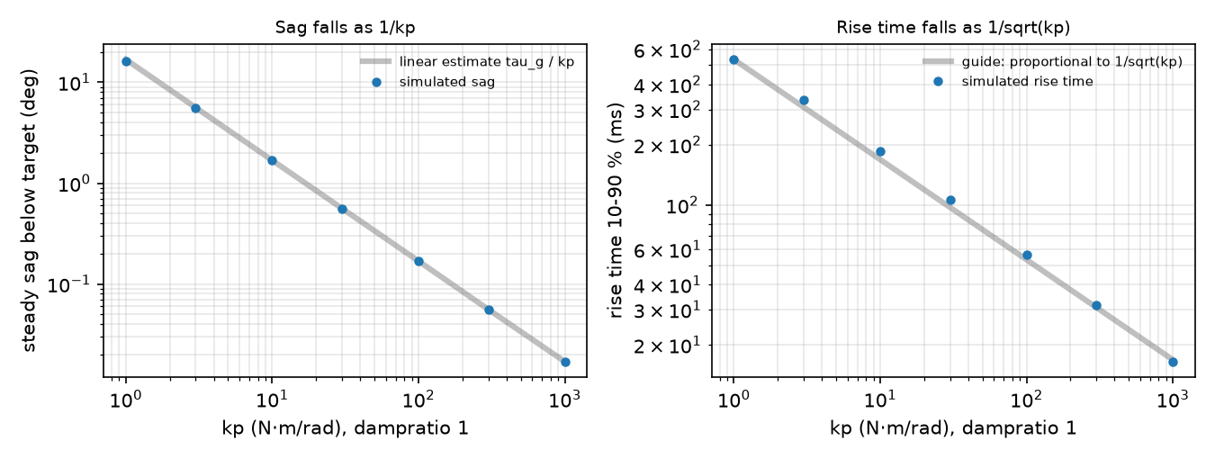
Observe. The sag equals the static balance to three decimals in every row; the linear is off only when the sag is large (kp = 1). A position servo with no integral term always sags under gravity: 0.017° at kp 1000, 16.193° at kp 1. Rise time falls as (kp 10 → 100: 185.6 → 56.7 ms). Removing the sag without huge gains is what gravity feedforward does in lesson 12.
Break it
Section titled “Break it”A · keep the SO-101 servo, drop the armature. kp 998.22, kv 2.731, joint damping 0.6, frictionloss 0.052, dt = 5 ms; sweep armature:
| armature | (kg·m²) | Euler | implicitfast | discrete | |
|---|---|---|---|---|---|
| 0.028 | 0.0320 | 0.88 | stable | stable | stable |
| 0.010 | 0.0140 | 1.34 | stable | stable | stable |
| 0.005 | 0.0090 | 1.67 | diverged | stable | stable |
| 0.002 | 0.0060 | 2.04 | diverged | stable | stable |
| 0.001 | 0.0050 | 2.23 | diverged | stable | stable |
| 0 | 0.0040 | 2.50 | diverged | stable | stable |
Euler fails first, already at = 1.67: it treats joint damping implicitly but the actuator’s kv explicitly, which is why the docs recommend implicitfast or implicit whenever kv is used (actuator/position/kv). With the Menagerie forcerange ±2.94 N·m added, Euler no longer explodes; it chatters (a fast, small back-and-forth around the target): peak-to-peak 0.629° at armature 0.001 and 0.798° at 0, a failure that looks like servo noise rather than numerics.
B · raise kp (implicitfast, armature 0.028): stable at kp 3000 ( = 1.53), diverged at kp 10000 ( = 2.80) and 30000 ( = 4.84); discrete stayed stable at all four. implicitfast treats damping implicitly but kp explicitly, which gives the bound with (Math details); the docs’ is the undamped case. With armature 0.028, is small and the limit sits just above 2. In A, removing the armature made tiny and large, so implicitfast survived = 2.50 while Euler, with kv explicit, failed at 1.67. Build it, Step 4 predicts every cell of A and B this way.
On the real robot
Section titled “On the real robot”The script reads the compiled SO-101 model (Menagerie · robotstudio_so101), home pose qpos0, dt = 5 ms:
| joint | kp | kv | forcerange (N·m) | armature | (kg·m²) | link part | without armature | |
|---|---|---|---|---|---|---|---|---|
| shoulder_pan | 998.22 | 2.731 | ±2.94 | 0.028 | 0.04446 | 0.01646 | 0.75 | 1.23 |
| shoulder_lift | 998.22 | 2.731 | ±2.94 | 0.028 | 0.04542 | 0.01742 | 0.74 | 1.20 |
| elbow_flex | 998.22 | 2.731 | ±2.94 | 0.028 | 0.03734 | 0.00934 | 0.82 | 1.63 |
| wrist_flex | 998.22 | 2.731 | ±2.94 | 0.028 | 0.02913 | 0.00113 | 0.93 | 4.71 |
| wrist_roll | 998.22 | 2.731 | ±2.94 | 0.028 | 0.02808 | 0.00008 | 0.94 | 17.62 |
| gripper | 998.22 | 2.731 | ±2.94 | 0.028 | 0.02802 | 0.00002 | 0.94 | 39.33 |
For the wrist and gripper the armature is almost the whole effective inertia; without it those joints would sit far past . Copying kp and kv without the armature into an Euler model reproduces Break it A. Whether the SO-101’s own implicitfast survives without armature was not tested; its large implicit kv raises the limit, so assume nothing.
Real hardware facts, from the LeRobot SO-101 guide: the follower uses six STS3215 servos with 1/345 gearing; the leader mixes 1/191, 1/345 and 1/147 so it can be moved by hand. The servos share one bus, each with a unique ID (shoulder pan 1 … gripper 6) stored in its EEPROM (non-volatile memory). The Menagerie comment states that its kp, kv and forcerange assume a servo proportional gain of 16 and are not a one-to-one mapping of LeRobot’s gains.
Procedure: command a 0.5 rad step on the real elbow, log the joint position through LeRobot, and compare rise time and sag with the simulated joint under the same load. Not yet measured on the real arm.
Check yourself
Section titled “Check yourself”Quick check · 2 questions. Click an answer.
1. You copy the SO-101 servo gains (kp 998.22, kv 2.731) into a model at dt = 5 ms but drop the armature. What does Euler do?
- It diverges already at armature 0.005 ( = 1.67), because it integrates the actuator’s
kvexplicitly. - Nothing changes, because armature only models the rotor for display.
- It stays stable down to = 2, exactly as the undamped limit says.
Why: Break it A, Euler diverges from 0.005 on while implicitfast and discrete stay stable; with explicit damping the bound becomes , below 2.
2. Why does the armature matter most for the SO-101’s wrist roll and gripper joints?
- Those joints carry the largest gravity torque.
- Their links are so light that the armature is almost their whole effective inertia; without it would be 17.62 and 39.33.
- They have the narrowest joint ranges, and armature acts as a soft limit.
Why: In the On the real robot table the link part is 0.00008 and 0.00002 kg·m² against an armature of 0.028; with it every joint stays below = 1.
- Easy. Replace
<position>by<motor>and sendctrl = 0. What does the link do? Whatctrlholds it horizontal? - Medium. Add
gear="2"to the position actuator, keep kp = 100. Does the sag change? Explain with the gear’s effect on length and force. - Hard. For Break it A, find the largest armature at which Euler diverges with kv = 0 (keep joint damping 0.6). Compare with the = 2 prediction.
Answers
Section titled “Answers”- It falls under gravity (zero torque). Holding it needs = 0.2943 N·m at .
gearscales both the actuator length and the force mapping, so the joint stiffness becomes gear² × kp: expect about a quarter of the sag. Measure it.- Undamped: , i.e. . The implicit joint damping widens the bound to , so divergence starts at a smaller armature; Build it’s
step_growthwith kv = 0 finds it before you run the sweep.
Takeaways and sources
Section titled “Takeaways and sources”<position>= PD with gains kp, kv; sag under gravity is (16.193° at kp 1, 0.017° at kp 1000), rise time ∝ .- Armature lowers . The SO-101’s 0.028 is most of the wrist and gripper inertia and keeps below 1 at 5 ms.
Eulerbreaks first (explicitkv),implicitfastonce (≈ 2 when damping is small),discreteheld in every tested case;step_growthpredicts each cell.
Next: lesson 06 · Rotations. Control on top of these actuators: lesson 12.
Sources