37 · Control rate and end-to-end latency
| Part | 9 · Sim to real |
| Run type | CPU · Mac or Colab CPU |
| Prerequisites | 12, 17 |
| Learn first | Stochastic Processes |
| Time | ~45 min |
| Code | experiments/37-latency/experiment.py |
| Status | ✅ done |
Act on this lesson
Tick each step when you have done it. Saved in this browser only.
A feedback loop does not care where the delay comes from; it only sees the sum, and the sum has a hard limit set by the loop’s own speed.
The problem
Section titled “The problem”A PD loop tuned in simulation (lesson 12) assumes the controller sees the joint now and its torque acts now. On a real robot the reading is old when it arrives, and the command is computed on a clock tick, sent over a bus and held until the next tick. LeRobot’s recording examples run the robot loop at 30 frames per second (guide): 33 ms steps before any compute time. How much delay can a loop take, why does it go unstable instead of “slower”, and what helps?
Before you read · 2 questions. Guess first; the lesson tells you why.
1. A joint loop works well at 1 kHz. You add a camera that delivers each reading 50 ms late but keep the controller at 1 kHz. How much delay does the loop now see?
- About 1 ms, because the controller still runs every millisecond.
- About 50 ms; control rate and latency are different knobs, and the loop only sees the total delay.
- None, as long as the camera’s frame rate is high.
Why: Core idea, consequences of the delay budget: a 1 kHz loop with 50 ms of camera delay is still a 50 ms loop. Sensor, filter, bus, compute and hold all add up.
2. You steer a car while watching a screen that shows the road half a second late. Why do hard corrections end in growing weaving instead of just a slower drive?
- The corrections arrive at the wrong moment, so each one feeds the next swing.
- The delay makes the steering weaker.
- A late screen shows a blurred image.
Why: A delay changes phase, not gain. In part A the loop goes from 4.45% overshoot without delay to 31.23% at 40 ms and is unstable at 50 ms.
Core idea
Section titled “Core idea”In plain words
Section titled “In plain words”Imagine steering a car by watching the road on a screen half a second late. With gentle corrections you manage. Steer hard and you correct for where the car was: you overshoot, see it late, correct back too hard, and the weaving grows until you leave the road. The delay did not make you slower; it made your corrections arrive at the wrong moment.
A feedback controller does the same: it pushes the joint based on an old reading. A gentle loop barely notices; a stiff, fast loop has already pushed too far when it sees the effect, and beyond some delay every correction feeds the next swing. The loop only sees the total delay (sensor, filter, bus, compute, waiting for the next tick), and the budget for that total is set by the loop itself: the faster it reacts, the less delay it can afford.
The latency chain
Section titled “The latency chain”flowchart TD
M["joint moves"] --> S["sensor sampling<br/>+ filtering"]
S --> B["bus / USB transfer<br/>OS scheduling"]
B --> C["compute<br/>estimator, policy"]
C --> H["command held<br/>until the next tick"]
H --> A["servo responds"]
A --> M
End-to-end latency is the time once around this chain: sensing (exposure, encoder sampling), filtering (a moving average adds , lesson 17), compute (a large model can take longer than a tick), bus round trips and OS scheduling, sample and hold (on average ), and the servo’s own response.
The delay budget, as code
Section titled “The delay budget, as code”Control engineers measure the budget with the phase margin. Every loop has a crossover frequency : roughly how fast it corrects, the frequency at which a correction comes back exactly as large as it went out. The phase margin is the timing slack left there before corrections arrive exactly out of step and reinforce the error. A delay eats of that slack. For a PD loop on one joint (Build it writes pd_delay_margin):
d = t_sense + t_filter + t_bus + t_compute + T / 2 # total delay (s); T = 1 / rate, add T if applied a tick latekd = 2 * zeta * sqrt(kp * I) # I = 0.0901 kg m^2, kp = 20, zeta = 0.7 -> kd = 1.879w_c, pm, d_max = pd_delay_margin(I, kp, kd) # 22.99 rad/s, 65.2 deg, 49.5 ms| Quantity | Formula |
|---|---|
| Loop (PD on an inertia) | |
| Crossover | |
| Phase margin | |
| Delay margin | |
| Delay added by a controller at rate | , plus per tick of compute |
is the joint inertia, , the PD gains, the Laplace variable (read it as “frequency”), the frequency where , PM in radians, the control rate and .
Consequences: a stiffer loop (higher ) tolerates less delay; at the limit it oscillates with period ; and a 1 kHz loop with 50 ms of camera delay is still a 50 ms loop.
Math details: why delay costs phase, and where T/2 comes from
A delay is pure phase. Delaying by multiplies the Laplace transform by ; at its gain is 1 and its angle .
Phase margin. A loop with one crossover is stable while its phase at stays above ; PM is the distance to . The delay does not move but subtracts there, so stability is lost when :
PD on an inertia. is a quadratic in . The double integrator contributes , the PD numerator gives back : that is PM at . At constant ζ, and , so PM stays the same while shrinks as (Break it: 98.9 ms at = 5, 49.5 ms at = 20).
Sample and hold. A zero-order hold, , has phase exactly : a delay of . Applying the command only at the next tick adds one : in total.
Assumptions. Linear loop, one crossover, no saturation (part D breaks the last one).
Go deeper: Stochastic Processes (AIEFS, signals over time); Lynch & Park, Modern Robotics, ch. 11; Tan et al., arXiv 1804.10332 (latency in sim-to-real).
Three mitigations
Section titled “Three mitigations”- Lower the loop gain: slower, but more margin.
- Predict: integrate a model over the delay from the delayed state with the commands already sent, and control the predicted present (the Smith-predictor idea; exact only when the model is, part C).
- Plan ahead in open loop: action chunking predicts several future actions per inference (lesson 31); LeRobot’s ACT defaults to
chunk_size = 100,n_action_steps = 100(configuration_act.py). While a chunk plays, the policy does not react to new observations.
Build it
Section titled “Build it”You will now write the delayed loop yourself. The joint is lesson 12’s simulate_joint from physai/control.py, so every trajectory can be compared with the Experiment’s MuJoCo loop sample by sample. The finished code is in physai/sim2real.py; uv run python experiments/37-latency/build.py runs the five steps (output in build_output.txt).
Step 1 · A delay line
Section titled “Step 1 · A delay line”A delay is a queue: push the newest reading, read the oldest. Until it has filled, it returns the first value.
class DelayLine:    """Returns the value pushed n ticks ago (the first value until the line has filled)."""
    def __init__(self, n, x0):        self.buf = deque([x0] * (n + 1), maxlen=n + 1)
    def __call__(self, x):        self.buf.append(x)        return self.buf[0]
== Step 1. A delay line of 3 ticks ==pushed [1, 2, 3, 4, 5, 6, 7, 8]read [0, 0, 0, 1, 2, 3, 4, 5]equals the history shifted by 3 (first value until filled): TrueStep 2 · The delay budget
Section titled “Step 2 · The delay budget”def pd_delay_margin(inertia, kp, kd): """Crossover w_c (rad/s), phase margin (rad) and delay margin PM / w_c (s) of PD on an inertia.""" w_c = np.sqrt((kd**2 + np.sqrt(kd**4 + 4 * inertia**2 * kp**2)) / (2 * inertia**2)) # |L(j w_c)| = 1 pm = np.arctan2(kd * w_c, kp) # the PD numerator's phase lead at w_c return w_c, pm, pm / w_c== Step 2. The delay budget of PD on an inertia ==Kd = 1.879: w_c = 22.99 rad/s, PM = 65.2 deg, d_max = PM / w_c = 49.5 ms|L(j w_c)| = 1.000000000000, phase of L = -114.8 deg = -180 + PMnp.roots of the crossover quartic: w = 22.9855 rad/s (ours 22.9855)|characteristic equation| at s = j w_c, d = d_max: 7.3e-15 (a pole sits on the imaginary axis)oscillation period at the boundary 2 pi / w_c = 273 msThe check needs no simulation: at the delayed characteristic equation has a root at , a pole on the imaginary axis.
Step 3 · PD that sees the past
Section titled “Step 3 · PD that sees the past”The controller is a callable object, so simulate_joint(torque_fn, …) runs it unchanged. see returns what the controller sees; the clock is for Step 4.
class DelayedPD:    """PD on one joint that sees it nd ticks late, recomputes every `period` s (None: every tick) and holds    the command in between; late=True applies each command one controller tick after computing it."""
    def __init__(self, kp, kd, target, dt, nd=0, period=None, late=False):        self.kp, self.kd, self.target, self.dt, self.nd = kp, kd, target, dt, nd        self.period, self.late = period, late        self.k, self.next_tick, self.u, self.queued, self.line, self.sent = 0, 0.0, 0.0, 0.0, None, []
    def see(self, q, qd):        """What the controller sees at this tick: the reading from nd ticks ago."""        if self.line is None:            self.line = DelayLine(self.nd, (q, qd))        return self.line((q, qd))
    def __call__(self, q, qd):        q_m, qd_m = self.see(q, qd)        if self.period is None or self.k * self.dt >= self.next_tick - 1e-12:   # a controller tick            self.next_tick += self.period or 0.0            u = self.kp * (self.target - q_m) - self.kd * qd_m            self.u, self.queued = (self.queued, u) if self.late else (u, u)        self.k += 1        self.sent.append(self.u)                   # torque applied during this tick        return self.u
Overshoot and stability follow the Experiment’s definitions:
def overshoot(q, target): """Overshoot past a positive step target in percent; None if the run diverged (|q| > 50).""" if not np.all(np.abs(q) < 50): return None return max(0.0, (q.max() - target) / target * 100)def is_stable(q, target): """Stable if the run stayed bounded and the late error (last quarter) is below 90% of the error in the second quarter, or below 1 mrad: a decaying response, not a sustained or growing oscillation.""" if overshoot(q, target) is None: return False e, n = np.abs(q - target), len(q) late, early = e[3 * n // 4:].max(), e[n // 4:n // 2].max() return late < 0.9 * early or late < 1e-3== Step 3. Delayed PD by hand vs the Experiment's MuJoCo loop ==delay ms ours % stable max |q_ours - q_mujoco| 0 4.45 yes 1.1e-16 10 4.51 yes 2.1e-17 20 5.02 yes 1.1e-16 30 11.51 yes 5.6e-17 40 31.23 yes 5.6e-17 50 215.84 NO 7.3e-15 60 diverges NO 5.7e-14stability boundary: stable at 48 ms, unstable at 49 ms (predicted d_max 49.5 ms)Your loop and MuJoCo’s agree to round-off at every delay, and the bisection lands where the Experiment’s did.
Step 4 · Control rate
Section titled “Step 4 · Control rate”With period set, the controller recomputes only on its ticks and holds the command; late=True applies each command one tick late. The last two columns are pure delays of and .
== Step 4. Control rate: sample and hold, and one tick of compute ==rate Hz T ms hold % +1 tick % delay T/2 % delay 3T/2 % 1000 1.0 4.45 4.46 4.45 4.46 100 10.0 4.48 4.61 4.47 4.62 50 20.0 4.55 10.31 4.51 11.51 30 33.3 4.75 78.07 4.72 215.84 20 50.0 5.34 diverges 6.66 diverges 10 100.0 diverges diverges 215.84 diverges30 Hz hold, ours vs the Experiment's MuJoCo loop: max diff 1.1e-16 radStep 5 · Predict over the delay
Section titled “Step 5 · Predict over the delay”The predictor overrides see: from the delayed reading it integrates with the torques already sent.
class PredictivePD(DelayedPD):    """DelayedPD that integrates the model I qdd = tau over the assumed delay (model_nd ticks) from the delayed    reading, with the torques it already sent, and controls that predicted present state."""
    def __init__(self, kp, kd, target, dt, nd, model_inertia, model_nd):        super().__init__(kp, kd, target, dt, nd)        self.model_inertia, self.model_nd = model_inertia, model_nd
    def see(self, q, qd):        q_m, qd_m = super().see(q, qd)        j = max(self.k - self.nd, 0)               # tick of the reading        for i in range(j, min(j + self.model_nd, self.k)):            qd_m += self.sent[i] / self.model_inertia * self.dt   # same semi-implicit Euler as the plant            q_m += qd_m * self.dt        return q_m, qd_m
== Step 5. Predict the present state over a 40 ms delay ==controller overshoot %no delay 4.45delay, no prediction 31.23prediction, exact model 4.45prediction, inertia +50% 0.00prediction, inertia -30% 9.44prediction, assumed delay 20 ms 4.70exact prediction vs no delay: max |q difference| = 0.0e+00 radinertia +50%, ours vs the Experiment's MuJoCo loop: max diff 5.6e-17 radWith the exact model the prediction is the true present, so the loop retraces the delay-free one bit for bit; the wrong models reproduce part C.
What you keep
Section titled “What you keep”physai.sim2real now has DelayLine, pd_delay_margin, DelayedPD, PredictivePD, overshoot and is_stable; lesson 38 identifies a delay, lesson 39 trains through one. tests/test_37_latency.py pins them to MuJoCo and SciPy: uv run pytest tests/test_37_latency.py.
Use it
Section titled “Use it”MuJoCo 3.17 holds the delay inside the model: actuators and sensors accept delay with a history buffer of nsample samples (interp: zero-order hold, linear or cubic; XML reference). SciPy’s frequency response gives the crossover numerically.
<actuator><motor joint="j" delay="0.039" nsample="39"/></actuator><sensor><jointpos joint="j" delay="0.039" nsample="39"/></sensor> <!-- or delay the readings -->loop = signal.TransferFunction([kd, kp], [I, 0, 0])w_c = optimize.brentq(lambda w: abs(signal.freqresp(loop, [w])[1][0]) - 1, 1.0, 1000.0)== Use it. MuJoCo's own delay buffer, SciPy's frequency response ==MuJoCo model overshoot % ours, delay ours %no delay attribute 4.46 1 ms 4.46sensors delay="0.039" nsample="39" 31.23 40 ms 31.23motor delay="0.039" nsample="39" 31.23 40 ms 31.23sensor delay 39 ms + reading sensordata after mj_step vs ours at 40 ms: max diff 5.6e-17 radSciPy freqresp + brentq: w_c = 22.9855 rad/s, PM = 65.16 deg, d_max = 49.47 ms (ours 22.9855, 65.16, 49.47)Why 39 ms and not 40: d.sensordata read after mj_step is already one tick old (the “no delay attribute” row behaves like 1 ms). A delayed motor shifts the whole response; the overshoot is the same.
| Tool | Call | Returns |
|---|---|---|
| physai | pd_delay_margin(I, kp, kd) | (rad/s), PM (rad), (s) |
| python-control | margin(sys) | gain margin, PM in degrees, phase-crossover, gain-crossover frequency (docs) |
| MATLAB | allmargin(sys) | PhaseMargin (degrees), PMFrequency, DelayMargin (sample periods for discrete-time models) (docs) |
Traps:
- Stale sensors.
sensordatais computed before integration; read aftermj_step, it is one step old, and that tick counts. - Degrees vs radians. needs PM in radians.
- Which crossover. The delay margin uses the gain crossover (); tools also return a phase crossover, often in the neighbouring slot.
Check after building · 2 questions.
1. In Build it, Step 2, the delayed characteristic equation is evaluated at s = j·22.99 rad/s with d = 49.5 ms and gives 7.3e-15. What does that show?
- The loop has no poles at all at that delay.
- The simulation has converged.
- A pole sits on the imaginary axis at the crossover frequency, so d_max = PM/ω_c is exactly the boundary between decaying and growing oscillation.
Why: The equation is checked without any simulation; Step 3’s bisection then measures the same boundary in the loop, stable at 48 ms and unstable at 49 ms.
2. In Use it, MuJoCo’s sensors get delay=“0.039” and the loop reproduces our 40 ms result (31.23%). Where does the missing millisecond come from?
- MuJoCo rounds every delay up to the next 10 ms.
- d.sensordata read after mj_step was computed before that step’s integration, so it is already one tick old.
- The motor adds a millisecond of response time.
Why: The “no delay attribute” row gives 4.46%, the same as our loop at 1 ms. That stale tick counts toward the delay budget.
Experiment
Section titled “Experiment”Full script: experiments/37-latency/experiment.py. MuJoCo 3.17.0, NumPy 2.5.4, Python 3.14, Apple Silicon Mac (Apple M5), deterministic, well under a minute of CPU.
A. Delay sweep. One joint as in lesson 12 ( = 0.0901 kg·m², no gravity), = 20, = 1.879 (ζ = 0.7), physics and control at 1 kHz, step 0 → 0.5 rad. The controller reads the joint seconds late (the loop of Build it, Step 3). Predict with the formula: = 22.99 rad/s, PM = 65.2°, so = 49.5 ms.
| delay [ms] | 0 | 5 | 10 | 20 | 30 | 40 | 50 | 60–100 |
|---|---|---|---|---|---|---|---|---|
| overshoot % | 4.45 | 4.47 | 4.51 | 5.02 | 11.51 | 31.23 | 215.84 | diverges |
| settle 2% [s] | 0.398 | 0.376 | 0.351 | 0.291 | 0.331 | 0.926 | never | never |
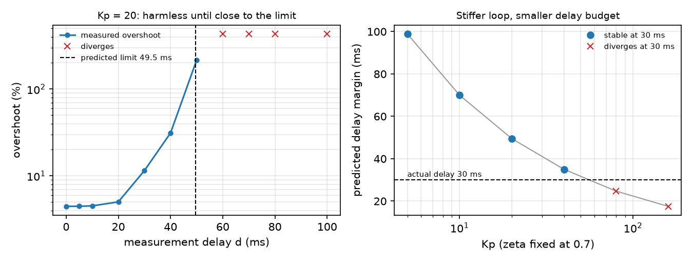
Bisection on whole milliseconds: stable at 48 ms, unstable at 49 ms, oscillating with a period of 272 ms ( = 273 ms). Up to about 20 ms the delay costs almost nothing; the last 20 ms before the limit cost everything.
B. Control rate. Same joint, no added delay, controller at Hz with zero-order hold (physics stays at 1 kHz). Second variant: the command is ready one tick later. Last two columns: part A at and .
| rate [Hz] | T [ms] | overshoot % | + 1 tick compute | A at T/2 | A at 3T/2 |
|---|---|---|---|---|---|
| 1000 | 1.0 | 4.45 | 4.46 | 4.45 | 4.46 |
| 100 | 10.0 | 4.48 | 4.61 | 4.47 | 4.62 |
| 50 | 20.0 | 4.55 | 10.31 | 4.51 | 11.51 |
| 30 | 33.3 | 4.75 | 78.07 (unstable) | 4.72 | 215.84 |
| 20 | 50.0 | 5.34 | diverges | 6.66 | diverges |
| 10 | 100.0 | diverges | diverges | 215.84 | diverges |
The rules predict the trend: 30 Hz applied at once behaves like 17 ms of delay (fine), with one tick of compute like 50 ms (past the limit).
C. Prediction at = 40 ms (the predictor of Build it, Step 5):
| controller | overshoot % | settle 2% [s] |
|---|---|---|
| no delay (reference) | 4.45 | 0.398 |
| delay, no prediction | 31.23 | 0.926 |
| delay + prediction, exact model | 4.45 | 0.398 |
| inertia +50% in the model | 0.00 | 0.223 |
| inertia −30% in the model | 9.44 | 0.491 |
| assumed delay 20 ms (true 40) | 4.70 | 0.300 |
With an exact model and no disturbances, prediction removes the delay completely; a wrong model still helps here but changes the response. Knowing the delay and the dynamics (lesson 38) is what makes prediction safe.
D. SO-101 at 30 Hz. Menagerie SO-101, shoulder_pan servo (2 ms step). An outer “policy” loop at 30 Hz nudges the servo target from delayed readings: target += K*T*(goal - q_delayed), = 10 s⁻¹. For an ideal servo, this integrator with delay is unstable when , above 140 ms (discrete-time analysis: from 5 ticks = 167 ms). The model servo is not ideal: alone, it reaches 50% of a 0.02 / 0.10 / 0.50 rad step after 18 / 44 / 110 ms, because it saturates on every step: with = 998 N·m/rad, 2.94/998 ≈ 3 mrad of error already demands its full 2.94 N·m, so a larger step takes longer.
| delay [ms] | 0 | 33 | 50 | 67 | 100 | 117 | 133 |
|---|---|---|---|---|---|---|---|
| goal 0.1 rad: overshoot % | 0.0 | 0.1 | 12.3 | 30.8 | 70.9 | 80.8 | 94.7 |
| goal 0.1 rad: late |e|/goal | 0.000 | 0.000 | 0.000 | 0.000 | 0.001 | 0.004 | 0.267 |
| goal 0.5 rad: overshoot % | 36.3 | 69.1 | 146.9 | 290.3 | 290.0 | 289.7 | 289.9 |
| goal 0.5 rad: late |e|/goal | 0.000 | 0.000 | 1.744 | 2.903 | 3.391 | 3.493 | 2.899 |
Small corrections keep oscillating only at 133 ms, near the ideal-servo estimate; a 0.5 rad move fails at 50 ms: the saturated servo adds its own, amplitude-dependent delay.
Break it
Section titled “Break it”Fix the delay at 30 ms and make the PD loop stiffer at constant ζ = 0.7 (right panel of the figure above):
| 5 | 10 | 20 | 40 | 80 | 160 | |
|---|---|---|---|---|---|---|
| [rad/s] | 11.49 | 16.25 | 22.99 | 32.51 | 45.97 | 65.01 |
| [ms] | 98.9 | 70.0 | 49.5 | 35.0 | 24.7 | 17.5 |
| overshoot % | 4.73 | 5.30 | 11.51 | 37.78 | diverges | diverges |
The damping ratio is the same in every row, yet the loop dies at = 80: stiffness raises , and the same 30 ms costs of phase. The formula predicts the failing rows exactly (24.7 and 17.5 ms are below 30 ms). Gains tuned in a zero-delay simulation are tuned for a loop that does not exist.
On the real robot
Section titled “On the real robot”- Measure the latency, do not guess it. LeRobot’s SO-101 follower times each bus and camera read in
get_observationand logs them at debug level (so_follower.py). Procedure: command a step on one joint, log command andPresent_Positiontime stamps, take the time until the reading moves. Not yet measured on the real arm. - The servo runs its own inner loop (part D): outer-loop latency costs reaction time, and stability when the policy reacts to its own delayed observations.
- Simulate the latency you will have (Tan et al. did, with system identification and an actuator model): put the measured delay into the training simulator (lesson 39), for example with MuJoCo’s
delayattribute.
Check yourself
Section titled “Check yourself”Quick check · 2 questions. Click an answer.
1. Overshoot is 4.45% without delay, 5.02% at 20 ms and 31.23% at 40 ms; at 50 ms the loop is unstable. Why does it fail so abruptly?
- The delay lowers the loop gain until the joint can no longer reach the target.
- The 1 kHz physics step becomes too coarse beyond 40 ms.
- The delay removes phase at the crossover; once that eats the 65.2° phase margin, at ms, corrections reinforce the error.
Why: Part A: predicted 49.5 ms, measured stable at 48 ms and unstable at 49 ms, oscillating with the predicted period (272 ms vs 273 ms). A delay changes phase, not gain.
2. In Break it the delay is fixed at 30 ms and Kp is raised at the same damping ratio ζ = 0.7. Why does the loop diverge at Kp = 80?
- A stiffer loop has a higher crossover frequency, so the same 30 ms costs more phase; its delay margin falls to 24.7 ms.
- A higher Kp at constant ζ means less damping, so it overshoots more.
- The torque limit is reached at Kp = 80.
Why: Break it table: 22.99 → 45.97 rad/s and 49.5 → 24.7 ms from Kp 20 to 80; the formula predicts both failing rows (24.7 and 17.5 ms are below 30 ms).
- Easy. A camera pipeline adds 40 ms, the policy runs at 20 Hz and its output is applied one tick after the frame. Estimate the total delay with the rule.
- Medium. Using , explain why part B’s 30 Hz loop with one tick of compute fails while part A at 40 ms survives.
- Hard. In part C, replace the exact predictor’s model with one that ignores the motor command (pure extrapolation ). Predict, then run: overshoot at 40 ms?
Answers
Section titled “Answers”- 40 ms + 50 ms (one tick of compute) + 25 ms (hold) = 115 ms.
- One tick of compute plus hold at 30 Hz is about = 50 ms, past the 49.5 ms margin; part A’s 40 ms is inside it (31.23% overshoot, stable).
- 15.15% overshoot, between exact prediction (4.45%) and none (31.23%), but settling takes 1.902 s (no prediction: 0.926 s): extrapolation ignores the acceleration the controller commanded during the delay. Row “extrapolation” in part C of
output.txt.
Takeaways and sources
Section titled “Takeaways and sources”- Delay removes phase ; the loop survives up to (predicted 49.5 ms, measured 48–49 ms, oscillating at the predicted 273 ms period).
- Control rate adds about , plus per tick of compute: here 30 Hz is fine applied at once, unstable with one tick of compute.
- Prediction with a correct model removes the delay (31.23% → 4.45%); stiffer loops and saturating actuators tolerate less.
Next: lesson 38 · System identification.
Sources:
- LeRobot · Imitation learning on real-world robots (30 fps examples,
lerobot-rollout,--inference.type=rtc; read 2026-10-27). - LeRobot
configuration_act.py,so_follower.py(Apache-2.0). - J. Tan et al., Sim-to-Real: Learning Agile Locomotion For Quadruped Robots, 2018.
- T. Zhao et al., Learning Fine-Grained Bimanual Manipulation with Low-Cost Hardware (ACT), 2023.
- MuJoCo Menagerie · robotstudio_so101 (Apache-2.0).
- Lynch & Park, Modern Robotics, ch. 11.
- All measured numbers:
experiments/37-latency/output.txt.