19 · Camera model, calibration and hand-eye calibration
| Part | 5 · Perception and estimation |
| Run type | CPU · Mac or Colab CPU |
| Prerequisites | 07 |
| Learn first | Image Fundamentals — Pixels, Channels, Color Spaces · Linear Systems |
| Time | ~60 min |
| Code | experiments/19-camera-calibration/experiment.py |
| Status | ✅ done |
Act on this lesson
Tick each step when you have done it. Saved in this browser only.
A camera is a 3×3 matrix, a few distortion numbers and a pose; calibration recovers them only if your data makes them observable.
The problem
Section titled “The problem”Every pixel-to-table computation (lesson 20) and every grasp from vision (lesson 21) multiplies by the camera matrix and the camera pose. A focal length 1 % off scales every lateral offset computed from the image by 1 %; a wrong camera-to-gripper transform shifts every grasp. OpenCV’s calibrateCamera almost always returns a small reprojection error, also when is wrong. This lesson calibrates a MuJoCo camera whose true is known, so you can see when the error number lies.
Before you read · 2 questions. Guess first; the lesson tells you why.
1. From 3 to 40 board views the training reprojection RMS stays at 0.088–0.093 px. What does that tell you about the focal length?
- It is already correct with 3 views, since the error does not improve.
- It is wrong by about 0.09 px.
- Nothing on its own - the focal error drops about 14-fold over the same range.
Why: The reprojection error measures how well the model fits these corners, not whether is right - error 0.292% with 3 views, 0.021% with 40. Ground truth is the only honest check.
2. To find where a wrist camera sits on the gripper (hand-eye), how should the arm move between the photos of a fixed board?
- Slide the gripper along one straight line without turning it, so the geometry stays simple.
- Rotate the wrist a lot, about different axes.
- Keep still and take many photos to average the noise.
Why: The mount is pinned down only if the wrist rotates about different axes. In Break it, a median 3.6° between poses gives a 27.18 mm error, 116.4° gives 1.33 mm.
Core idea
Section titled “Core idea”In plain words
Section titled “In plain words”A camera is a function from a 3D point to a pixel. The extrinsics say where the camera is and which way it looks: a rigid transform from the world into the camera’s frame (lesson 07). The intrinsics describe the inside: the focal length in pixels and where the optical axis hits the image (the principal point). A few distortion coefficients describe how a real lens bends straight lines.
Calibration fits those parameters to a checkerboard whose corners you know to the millimetre: detect the corners, then search for the parameters whose predicted pixels land on them. The leftover mismatch is the reprojection error. Like a training loss, it says how well the model fits these examples, not whether the parameters are right. A board held flat in front of the camera is the classic trap: “long lens, board far away” and “short lens, board close” produce the same picture.
Hand-eye calibration finds where a wrist camera sits on the gripper. The gripper pose comes from the joint angles, the board pose from the image; the board never moves, so every pair of arm poses gives one equation for the unknown mount, which is pinned down only if the wrist rotates about different axes.
The camera as a pipeline
Section titled “The camera as a pipeline”flowchart TD
W["3D point in the world<br/>(a board corner)"] --> C["point in the camera frame<br/>X_c = R · X_w + t<br/>(extrinsics)"]
C --> N["divide by depth<br/>x / z, y / z"]
N --> D["lens distortion<br/>k1, k2, k3, p1, p2"]
D --> P["pixel (u, v)<br/>scale by fx, fy, shift by cx, cy<br/>(intrinsics K)"]
P -. "compare with the<br/>detected corner" .-> E["reprojection error<br/>(what calibration minimizes)"]
The camera, as code
Section titled “The camera, as code”X_c = R @ X_w + t # world -> camera (x right, y down, z forward), metresx, y = X_c[0] / X_c[2], X_c[1] / X_c[2] # divide by depth: farther points move less on the imageu, v = fx * x + cx, fy * y + cy # to pixels (distortion bends x, y just before this line)fy = (height / 2) / np.tan(np.radians(fovy) / 2) # MuJoCo: 480 px tall, fovy 50 deg -> 514.68 px# calibration: K, dist and one (R_i, t_i) per view that minimize the squared pixel error over all corners| Piece | Formula |
|---|---|
| Projection | |
| Intrinsics | |
| Extrinsics | |
| Radial distortion | |
| of a MuJoCo camera | |
| Hand-eye |
: pixel; : point in the camera frame; : equal up to scale; : focal lengths (px); : principal point; : world to camera; , ; : radial coefficients; : image size; : camera pose in the gripper frame; , : measured gripper and board motions (Math details).
Math details: conventions, Zhang's method and the hand-eye equation
Pinhole model (Hartley & Zisserman, camera models). The camera frame follows OpenCV: right, down, forward. Distortion acts on the normalized coordinates before ; besides the radial part there are tangential terms (OpenCV calib3d).
K from MuJoCo. fovy is the vertical field of view in degrees; the horizontal one follows from the image size (MuJoCo XML · camera/fovy), so pixels are square and . The in is OpenCV’s convention that pixel centres sit on integer coordinates. MuJoCo cameras look along their axis with up, so the axes flip: for the camera-to-world rotation (cam_xmat) , and for the world-to-camera the factor goes on the left: .
Calibration. calibrateCamera follows Zhang’s planar method (Zhang 2000): intrinsics from the plane-to-image homographies (3×3 maps from board points to pixels), board poses, then Levenberg–Marquardt on the total reprojection error. Build it writes all three.
Why flat boards fail. For a board parallel to the image at depth , : only the ratio is constrained. Tilt makes vary across the board, and the varying foreshortening separates from .
Hand-eye. With gripper poses (forward kinematics), board poses in the camera (PnP: camera pose from known 3D points and their pixels) and the board fixed in the base, , which gives
Park & Martin’s closed form (Park & Martin 1994): with rotation vectors , and , ; then from the stacked linear system . OpenCV’s calibrateHandEye offers this and four other methods, and needs at least two motions with non-parallel rotation axes. When the rotations are small, and the translation is poorly determined.
Go deeper: Image Fundamentals — Pixels, Channels, Color Spaces, Linear Systems; Zhang 2000; Park & Martin 1994; Hartley & Zisserman (book page).
Build it
Section titled “Build it”You will now write the camera model, Zhang’s calibration and the hand-eye solver in NumPy and check every step. The data are the Experiment’s: the same rendered board views (same seed), the corners OpenCV detects in them, and the SO-101 poses. OpenCV only finds corners and referees.
Type the steps into a file of your own and run it after each step. The finished functions are in physai/vision.py; uv run python experiments/19-camera-calibration/build.py runs all five steps with the checks (output in build_output.txt).
Step 1 · K and the projection
Section titled “Step 1 · K and the projection”def intrinsics_from_fovy(fovy, width, height): """Camera matrix K of a MuJoCo camera: square pixels, vertical field of view fovy (degrees).""" f = (height / 2) / np.tan(np.radians(fovy) / 2) return np.array([[f, 0.0, (width - 1) / 2], [0.0, f, (height - 1) / 2], [0.0, 0.0, 1.0]])def project_points(X, R, t, K, dist=(0.0, 0.0, 0.0, 0.0, 0.0)): """World points X (N, 3) to pixels (N, 2). R, t: world -> camera; dist = (k1, k2, p1, p2, k3), OpenCV's order.""" Xc = X @ R.T + t # camera frame: x right, y down, z forward x, y = Xc[:, 0] / Xc[:, 2], Xc[:, 1] / Xc[:, 2] # divide by depth k1, k2, p1, p2, k3 = dist r2 = x * x + y * y radial = 1 + k1 * r2 + k2 * r2**2 + k3 * r2**3 xd = x * radial + 2 * p1 * x * y + p2 * (r2 + 2 * x * x) # tangential terms p1, p2 yd = y * radial + p1 * (r2 + 2 * y * y) + 2 * p2 * x * y return np.c_[K[0, 0] * xd + K[0, 1] * yd + K[0, 2], K[1, 1] * yd + K[1, 2]]The distortion terms follow OpenCV’s order and formula. Check against the Experiment’s ground truth, the projection of each true board pose against the corners detected in MuJoCo’s images, and the distorted projection against cv2.projectPoints:
== Step 1. K from fovy and the pinhole projection ==fovy 50 deg, 640x480: fx = fy = 514.68 px, cx = 319.5, cy = 239.5 max |K - Experiment's k_true()| = 0.0e+0060 rendered views: detected corners vs our projection, mean 0.220 px, max 0.525 pxwith dist (k1, k2, p1, p2, k3) = (-0.15, 0.03, 0.001, -0.002, 0.01): max |ours - cv2.projectPoints| = 2.6e-13 pxThese are the Experiment’s corner-detection numbers: MuJoCo renders an ideal pinhole, so what is left is the detector. With distortion your code and OpenCV agree to 1e-13 px.
Step 2 · One homography per view
Section titled “Step 2 · One homography per view”The board is a plane, so its corners map to pixels by a 3×3 homography (Math details). Each corner gives two linear equations in the nine entries of ; the best solution of the stacked system is the last right singular vector. Moving both point sets to unit scale first (Hartley’s normalization) keeps the system well conditioned.
def homography_dlt(src, dst): """3x3 H with dst ~ H src from N >= 4 point pairs (N, 2 arrays): the normalized direct linear transform.""" def normalizer(p): # centroid to 0, mean distance to sqrt(2) c = p.mean(axis=0) s = np.sqrt(2) / np.mean(np.linalg.norm(p - c, axis=1)) return np.array([[s, 0, -s * c[0]], [0, s, -s * c[1]], [0, 0, 1]]) Ts, Td = normalizer(src), normalizer(dst) a = np.c_[src, np.ones(len(src))] @ Ts.T b = np.c_[dst, np.ones(len(dst))] @ Td.T A = [] for (x, y, _), (u, v, _) in zip(a, b): # u = (h1 . a) / (h3 . a), same for v: two rows A.append([x, y, 1, 0, 0, 0, -u * x, -u * y, -u]) A.append([0, 0, 0, x, y, 1, -v * x, -v * y, -v]) Hn = np.linalg.svd(np.array(A))[2][-1].reshape(3, 3) # least-squares null vector of A H = np.linalg.inv(Td) @ Hn @ Ts # undo the normalization return H / H[2, 2]== Step 2. One homography per view (board plane -> pixels) ==RMS distance of the 54 corners from H(board point): 0.091 pxmax |ours - cv2.findHomography| = 0.0068 px, max |ours - true K[r1 r2 t]| = 0.352 pxon exact projected corners: max |ours - true| = 2.3e-13 pxExact on exact corners (2.3e-13 px); on detected corners within 0.0068 px of cv2.findHomography (which refines a slightly different error) and 0.352 px from the true homography: the detection error again.
Step 3 · Zhang’s closed form
Section titled “Step 3 · Zhang’s closed form”Each homography is . Because and are orthonormal, every view gives two linear equations in the six entries of : and . Stack them, take the null vector, and read out of (Zhang 2000, section 3.1):
def zhang_intrinsics(Hs): """Closed-form K from >= 3 board-to-image homographies (Zhang 2000); also returns the singular values of V.""" def v(H, i, j): # h_i^T B h_j as a linear function of b a, c = H[:, i], H[:, j] return np.array([a[0] * c[0], a[0] * c[1] + a[1] * c[0], a[1] * c[1], a[2] * c[0] + a[0] * c[2], a[2] * c[1] + a[1] * c[2], a[2] * c[2]]) V = np.array([row for H in Hs for row in (v(H, 0, 1), v(H, 0, 0) - v(H, 1, 1))]) _, sv, Vt = np.linalg.svd(V) b11, b12, b22, b13, b23, b33 = Vt[-1] * np.sign(Vt[-1][0]) # B = K^-T K^-1, up to scale cy = (b12 * b13 - b11 * b23) / (b11 * b22 - b12**2) lam = b33 - (b13**2 + cy * (b12 * b13 - b11 * b23)) / b11 fx = np.sqrt(lam / b11) fy = np.sqrt(lam * b11 / (b11 * b22 - b12**2)) skew = -b12 * fx**2 * fy / lam cx = skew * cy / fy - b13 * fx**2 / lam return np.array([[fx, skew, cx], [0.0, fy, cy], [0.0, 0.0, 1.0]]), sv== Step 3. Zhang's closed form: K from the homographies ==from the 60 true homographies: max |K - K_true| = 8.3e-13 px views fx fy cx cy skew fx err % 3 511.70 512.07 319.94 238.44 0.135 0.579 5 513.44 513.44 319.45 239.33 0.097 0.242 10 514.89 514.85 318.71 239.23 0.003 0.040 20 514.40 514.38 319.00 239.51 -0.022 0.055 60 514.40 514.47 319.28 239.32 0.031 0.054singular values of V / largest, 10 views (the last one is the solution, the one before decides): tilt 35 deg: 1.0e+00 9.6e-01 2.7e-01 7.7e-04 3.4e-04 2.3e-09 tilt 0 deg: 1.0e+00 8.6e-01 1.2e-03 3.6e-06 6.7e-07 1.1e-11 -> fx = 24982 pxOn exact homographies the formula returns to 8.3e-13 px. On detected corners it stalls near 0.05 % focal error: it minimizes an algebraic quantity, not pixels, which Step 4 fixes. The singular values show the Break it failure before any fit: the second-smallest is 3.4e-4 of the largest with tilted boards and 6.7e-7 with flat ones, so two directions of fit almost equally well and the “solution”, = 24982 px, is noise.
Step 4 · Poses, then Levenberg–Marquardt
Section titled “Step 4 · Poses, then Levenberg–Marquardt”With known, is a scaled ; complete and snap to the nearest rotation:
def pose_from_homography(H, K): """Board pose (R, t) in the camera from its homography: K^-1 H = scale * [r1 r2 t].""" A = np.linalg.inv(K) @ H s = np.sign(A[2, 2]) / np.linalg.norm(A[:, 0]) # the board lies in front: t_z > 0 r1, r2, t = s * A[:, 0], s * A[:, 1], s * A[:, 2] U, _, Vt = np.linalg.svd(np.c_[r1, r2, np.cross(r1, r2)]) return U @ Vt, t # nearest rotation matrixThese starts are good to 0.090° and 0.44 mm. The final fit minimizes the squared pixel errors over and all 60 poses at once, with a finite-difference Jacobian built one view at a time (a pose only moves its own view’s pixels); the damping chooses between a Gauss–Newton step and a short gradient step. Rotations are updated as :
def rotvec_to_mat(w): """Rotation vector (axis * angle, rad) to a 3x3 matrix (Rodrigues' formula, safe at w = 0).""" a = np.linalg.norm(w) k = np.array([[0, -w[2], w[1]], [w[2], 0, -w[0]], [-w[1], w[0], 0]]) if a < 1e-12: return np.eye(3) + k return np.eye(3) + np.sin(a) / a * k + (1 - np.cos(a)) / a**2 * (k @ k)def mat_to_rotvec(R): """3x3 rotation matrix to its rotation vector (angle below pi).""" a = np.arccos(np.clip((np.trace(R) - 1) / 2, -1.0, 1.0)) v = np.array([R[2, 1] - R[1, 2], R[0, 2] - R[2, 0], R[1, 0] - R[0, 1]]) return v / 2 if a < 1e-12 else a / (2 * np.sin(a)) * vdef refine_calibration(obj, views, K, poses, iters=10): """Levenberg-Marquardt on the total reprojection error over fx, fy, cx, cy, k1, k2 and every board pose.
obj: (N, 3) board corners; views: list of (N, 2) detected pixels; poses: list of (R, t) starting guesses. Pose i moves by a small correction c_i = (w, dt): R @ rotvec_to_mat(w), t + dt. Returns K, dist, poses, RMS. """ def view_residual(q, pose, c, uv): # q = (fx, fy, cx, cy, k1, k2) Kq = np.array([[q[0], 0.0, q[2]], [0.0, q[1], q[3]], [0.0, 0.0, 1.0]]) R, t = pose[0] @ rotvec_to_mat(c[:3]), pose[1] + c[3:] return (project_points(obj, R, t, Kq, (q[4], q[5], 0.0, 0.0, 0.0)) - uv).ravel()
def residual(q, c): return np.concatenate([view_residual(q, p, ci, uv) for p, ci, uv in zip(poses, c, views)])
n, m = len(views), 2 * len(obj) q, c = np.r_[K[0, 0], K[1, 1], K[0, 2], K[1, 2], 0.0, 0.0], np.zeros((n, 6)) r, damping = residual(q, c), 1e-3 for _ in range(iters): J = np.zeros((n * m, 6 + 6 * n)) # pose i only moves the pixels of view i for i, (p, uv) in enumerate(zip(poses, views)): rows, x = slice(i * m, (i + 1) * m), np.r_[q, c[i]] for j in range(12): # forward differences: 6 shared + 6 own parameters h = 1e-6 * max(1.0, abs(x[j])) xh = x.copy() xh[j] += h J[rows, j if j < 6 else 6 * i + j] = (view_residual(xh[:6], p, xh[6:], uv) - r[rows]) / h JtJ = J.T @ J step = np.linalg.solve(JtJ + damping * np.diag(np.diag(JtJ)), -J.T @ r) q_new, c_new = q + step[:6], c + step[6:].reshape(n, 6) r_new = residual(q_new, c_new) if r_new @ r_new < r @ r: # better: accept, trust the linear model more q, c, r, damping = q_new, c_new, r_new, damping / 10 else: # worse: reject, take a shorter step damping *= 10 Kq = np.array([[q[0], 0.0, q[2]], [0.0, q[1], q[3]], [0.0, 0.0, 1.0]]) new = [(R @ rotvec_to_mat(ci[:3]), t + ci[3:]) for (R, t), ci in zip(poses, c)] return Kq, np.array([q[4], q[5], 0.0, 0.0, 0.0]), new, np.sqrt(2 * np.mean(r**2))== Step 4. Poses from the homographies, then Levenberg-Marquardt on all 60 views ==start poses vs truth: median 0.090 deg, 0.44 mm fx fy cx cy k1 k2 RMS pxours (k1, k2) 514.56 514.55 319.30 239.25 +0.0034 -0.0214 0.091cv2.calibrateCamera, k1 k2 only 514.56 514.55 319.30 239.25 +0.0034 -0.0214 0.091cv2.calibrateCamera, default 5 coef 514.58 514.58 319.57 239.33 +0.0005 +0.0461 0.091max |K ours - K cv2 (same model)| = 7.0e-08 px, fx error vs truth 0.025 %fitted poses vs truth: median 0.051 deg, 0.49 mmYour fit and cv2.calibrateCamera with the same model ( only) agree to 7.0e-08 px. OpenCV’s default model adds ; that is the Experiment’s “all 60 views” line (514.58, 319.57, 239.33). On a lens without any distortion the extra coefficients shift by 0.27 px and the RMS stays 0.091 px: another fit the error number cannot judge.
Step 5 · Hand-eye
Section titled “Step 5 · Hand-eye”def hand_eye_park(As, Bs): """Solve A X = X B (Park & Martin 1994). As: gripper motions, Bs: camera motions (4x4); X: camera in gripper.""" M = sum(np.outer(mat_to_rotvec(B[:3, :3]), mat_to_rotvec(A[:3, :3])) for A, B in zip(As, Bs)) w, V = np.linalg.eigh(M.T @ M) Rx = V @ np.diag(w ** -0.5) @ V.T @ M.T # rotation: (M^T M)^(-1/2) M^T C = np.vstack([A[:3, :3] - np.eye(3) for A, _ in zip(As, Bs)]) d = np.concatenate([Rx @ B[:3, 3] - A[:3, 3] for A, B in zip(As, Bs)]) X = np.eye(4) X[:3, :3], X[:3, 3] = Rx, np.linalg.lstsq(C, d, rcond=None)[0] # translation: (R_A - I) t = R_X t_B - t_A return Xcv2.calibrateHandEye is missing from the OpenCV 5.0.0 Python build used here, so the Experiment uses this solver too. The check replays its loop with the same seed:
== Step 5. Hand-eye AX = XB on the Experiment's SO-101 poses (same seed, 15 poses, 20 trials) ==true camera offset in the gripper frame: 76.0 mm rot noise deg trans noise mm X rot err deg X trans err mm max |X ours - X Exp.| 0 0 0.000 0.00 1.8e-15 0.1 0.5 0.050 0.31 2.3e-14 0.2 1 0.105 0.68 9.5e-14 0.5 2 0.177 1.55 2.7e-14 1 5 0.389 2.84 1.9e-12 2 10 0.905 6.87 8.2e-15These are the Experiment table’s numbers row by row; your equals the Experiment’s to 1e-12 (mat_to_rotvec replaces cv2.Rodrigues).
What you keep
Section titled “What you keep”physai.vision now has intrinsics_from_fovy, project_points, homography_dlt, zhang_intrinsics, pose_from_homography, rotvec_to_mat, mat_to_rotvec, refine_calibration and hand_eye_park. Lesson 20 reuses homography_dlt and project_points on the way back from pixels to the table. tests/test_19_camera_calibration.py pins them to exact synthetic data, SciPy and OpenCV; run uv run pytest tests/test_19_camera_calibration.py after you change anything.
Use it
Section titled “Use it”OpenCV does the whole pipeline: detect, refine, calibrate, then check on held-out views.
objp = board_corners_m.astype(np.float32) # (54, 3), z = 0, in metres: sets the unit of tok, c = cv2.findChessboardCorners(gray, (9, 6)) # inner corners (columns, rows)c = cv2.cornerSubPix(gray, c, (5, 5), (-1, -1), criteria) # sub-pixel refinementrms, K, dist, rvecs, tvecs = cv2.calibrateCamera([objp] * n, views, (640, 480), None, None) # size = (width, height)_, rvec, tvec = cv2.solvePnP(objp, held_out, K, dist) # board pose under the estimated Kpx, _ = cv2.projectPoints(objp, rvec, tvec, K, dist) # reproject and comparecalibrateCameraExtended returns the same plus the standard deviation of every intrinsic: report it with the RMS. Other tools name the same pieces differently:
| Piece | This lesson / physai | OpenCV | MuJoCo | ROS sensor_msgs/CameraInfo |
|---|---|---|---|---|
| intrinsics | cameraMatrix | fovy + image size, or focal/principal/sensorsize | k, 9 values, row-major | |
| distortion | dist = | distCoeffs, same order | no attribute: ideal pinhole | d with distortion_model "plumb_bob": |
| camera axes | right, down, forward | same | right, up, looks along | optical frame: right, down, into the image |
| board pose | , world to camera | rvec (rotation vector), tvec | — | — |
Sources: OpenCV calib3d, MuJoCo XML · camera, CameraInfo.msg.
Traps:
- Image size is (width, height).
calibrateCameratakes(640, 480); the NumPy image is(480, 640). Passgray.shape[::-1]. - Units come from
objp. Squares in millimetres givetvecin millimetres. A board printed at 98 % scale makes every translation 2 % wrong and leaves the RMS untouched. - MuJoCo’s camera is not OpenCV’s. Flip and (
diag(1, -1, -1), Math details) before you compare poses; forgetting it puts the board behind the camera.
Check after building · 2 questions.
1. In Build it, Step 3, Zhang’s closed form on 10 flat boards returns = 24982 px. What do the singular values of show?
- The second-smallest falls from 3.4e-4 (tilted) to 6.7e-7 of the largest, so two directions of fit almost equally well and the answer is noise.
- The smallest one is exactly zero, which means the homographies are exact.
- All six are equal, so the corners were not detected.
Why: The last singular vector is the solution; the one before decides whether it is unique. Step 3 prints 3.4e-4 at 35° tilt and 6.7e-7 at 0° - the flat-board ambiguity of Break it, visible before any fit.
2. Your Levenberg–Marquardt fit matches cv2.calibrateCamera with only to 7.0e-08 px, but OpenCV’s default call gives = 319.57 instead of 319.30. Why?
- OpenCV uses float32 and loses precision.
- Your finite-difference Jacobian is not accurate enough.
- The default model also fits , which trade against on a lens without distortion while the RMS stays 0.091 px.
Why: Step 4 prints all three rows with the same 0.091 px RMS - another fit the error number cannot judge. Both focal lengths stay within 0.025 % of the truth.
Experiment
Section titled “Experiment”Setup. A 9×6 inner-corner checkerboard with 25 mm squares, built from box geoms (exact geometry), moved as a mocap body (placed directly, without physics) to random poses (±35° tilt about x and y, ±20° about z) 0.5–0.65 m in front of a 640×480 camera with fovy = 50. Ground truth: px, , . Corners from findChessboardCorners + cornerSubPix. 60 training views, 15 held-out views (a test set): estimate each held-out board pose with solvePnP under the estimated and distortion, then reproject.
r.update_scene(d, camera="cam"); img = r.render()ok, c = cv2.findChessboardCorners(gray, (9, 6))c = cv2.cornerSubPix(gray, c, (5, 5), (-1, -1), crit)rms, K, dist, _, _ = cv2.calibrateCamera([objp] * n, views, (640, 480), None, None)Predict. Few views should give a small training error but a wrong .
Run uv run python experiments/19-camera-calibration/experiment.py (MuJoCo 3.17.0, OpenCV 5.0.0, NumPy 2.5.4, Apple M5, deterministic: two runs gave identical output).
The renderer is an ideal pinhole camera: detected corners sit 0.220 px (mean), 0.525 px (max) from the projection with the ground-truth . With all 60 views: , , , , training RMS 0.091 px.
| Views | Train RMS (px) | Held-out RMS (px) | error (%) | error (%) | error (px) | error (px) |
|---|---|---|---|---|---|---|
| 3 | 0.088 | 0.103 | 0.292 | 0.230 | 1.17 | 0.89 |
| 5 | 0.089 | 0.101 | 0.145 | 0.146 | 0.93 | 0.54 |
| 10 | 0.093 | 0.101 | 0.066 | 0.064 | 0.41 | 0.30 |
| 20 | 0.093 | 0.101 | 0.043 | 0.046 | 0.40 | 0.24 |
| 40 | 0.091 | 0.101 | 0.021 | 0.025 | 0.23 | 0.18 |
(median of 10 random subsets per row)
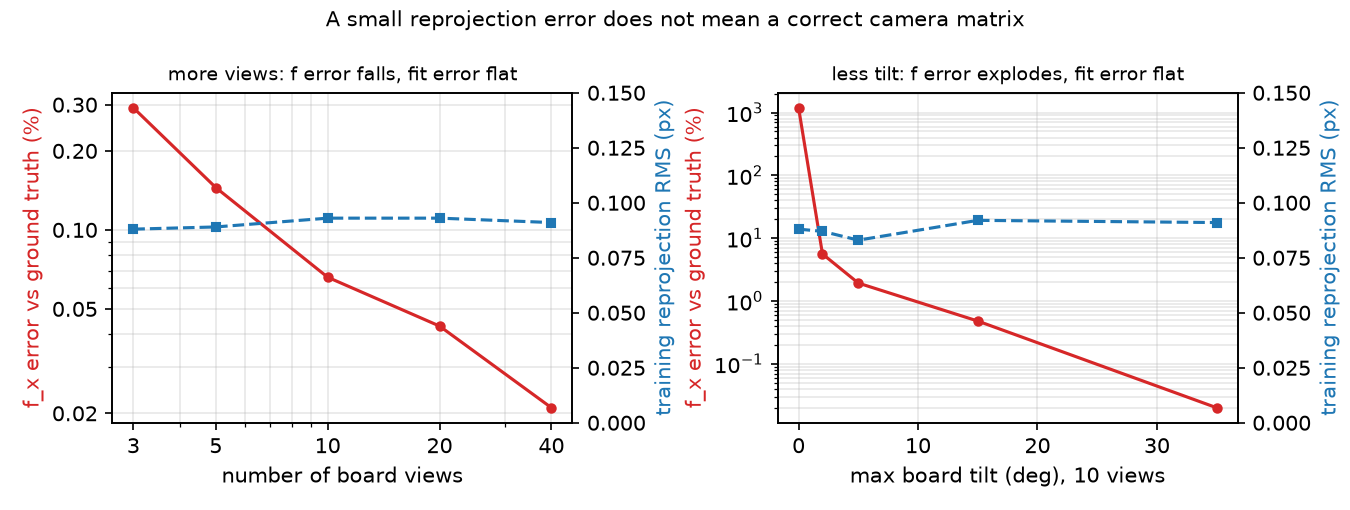
Observe. The training RMS is flat (0.088–0.093 px) while the focal error drops about 14-fold from 3 to 40 views. The held-out RMS is just as flat (0.101–0.103 px): solvePnP re-fits each held-out pose and absorbs a small focal error, so it only flags gross failures (2.441 px in the tilt test below). Ground truth is the only honest check; on a real camera, add the parameter standard deviations from calibrateCameraExtended.
Distortion. We warp 20 views with a known (cv2.remap). Calibration recovers with 0.096 % focal error. Forcing distortion to zero on the same views raises the RMS to 0.252 px and the focal error to 1.24 %: an unmodeled lens bends .
Hand-eye. SO-101 gripper poses from forward kinematics at random joint angles (60 % of each range); is the Menagerie wrist_cam pose in the gripper frame (offset 76.0 mm). Noise on the board-in-camera poses stands in for PnP errors; 15 poses per solve, 20 trials, Park & Martin’s solver.
| Rotation noise (deg) | Translation noise (mm) | rotation error (deg) | translation error (mm) |
|---|---|---|---|
| 0 | 0 | 0.000 | 0.00 |
| 0.1 | 0.5 | 0.050 | 0.31 |
| 0.2 | 1 | 0.105 | 0.68 |
| 0.5 | 2 | 0.177 | 1.55 |
| 1 | 5 | 0.389 | 2.84 |
| 2 | 10 | 0.905 | 6.87 |
Exact data gives exact ; with 105 motion pairs the error stays below the per-pose noise.
Break it
Section titled “Break it”Remove the tilt. 10 views, tilt limited to ±t:
| Tilt (deg) | Train RMS (px) | Held-out RMS (px) | error (%) |
|---|---|---|---|
| 0 | 0.088 | 2.441 | 1193 |
| 2 | 0.087 | 0.179 | 5.61 |
| 5 | 0.083 | 0.114 | 1.93 |
| 15 | 0.092 | 0.102 | 0.48 |
| 35 | 0.091 | 0.101 | 0.02 |
With fronto-parallel boards (facing the camera squarely) the training RMS is still 0.088 px and the focal length is off by 1193 %: a longer lens and a farther board explain the same corners (Math details; Build it, Step 3 shows it in the linear system). OpenCV’s calibrateCamera docs ask for “multiple board poses with significant tilt” (calib3d.hpp).
Remove the rotation diversity (hand-eye, noise 0.5° / 2 mm, joints sampled in a fraction of their range; a fresh random pose pool per row):
| Range fraction | Median rotation between poses (deg) | rotation error (deg) | translation error (mm) |
|---|---|---|---|
| 0.02 | 3.6 | 4.818 | 27.18 |
| 0.05 | 9.2 | 2.200 | 13.68 |
| 0.1 | 18.8 | 0.977 | 4.89 |
| 0.3 | 54.8 | 0.348 | 1.85 |
| 0.6 | 116.4 | 0.274 | 1.33 |
Translation enters through ; when the arm barely rotates, and noise is divided by a near-zero matrix: the hand-eye version of the flat board.
On the real robot
Section titled “On the real robot”- The Menagerie SO-101 has a
wrist_camwithfovy = 61in its model file (robotstudio_so101); a real webcam has its own and distortion. Not yet measured on the real arm. - Intrinsics: print a checkerboard, measure the squares with calipers (scale error goes straight into ), glue it flat, take 20+ views with strong tilt and varied distance, and check held-out error and parameter standard deviations, not only the RMS.
- Hand-eye: fix the board, move the arm through 15+ poses with large wrist rotations, record joint angles (forward kinematics, lesson 08) and the PnP board pose, then solve . Joint-angle errors and servo backlash (play in the gears) enter directly.
- Autofocus and auto-zoom change ; lock them before calibrating.
Check yourself
Section titled “Check yourself”Quick check · 2 questions. Click an answer.
1. With boards held parallel to the image (0° tilt), the training RMS is 0.088 px but the focal length is off by 1193%. Why?
- Corner detection fails on flat boards.
- For a plane parallel to the image only is constrained, so a longer lens and a farther board explain the same corners.
- Lens distortion is strongest at 0° tilt.
Why: Tilt makes the depth vary across the board, and the foreshortening separates from - 5° of tilt already brings the error down to 1.93%, 35° to 0.02% (Break it).
2. Twenty views are warped with a known . What happens if you calibrate them with distortion forced to zero?
- The RMS rises to 0.252 px and the focal length is off by 1.24 %; the missing lens model bends .
- Nothing changes; distortion only affects the image corners, not .
- Calibration fails with an error because the corners are curved.
Why: Experiment, Distortion - with free the fit recovers at 0.096 % focal error; forced to zero, the RMS is 0.252 px and the focal error 1.24 %.
- Easy. Compute for a 1280×720 image and
fovy = 61. - Medium. Why is a 0.09 px training RMS no evidence of a good calibration? Point to the two tables.
- Hard. Set
CALIB_FIX_ASPECT_RATIOandCALIB_FIX_PRINCIPAL_POINTand repeat the 0° tilt row. Does fixing parameters rescue the degenerate case?
Answers
Section titled “Answers”- ; px.
- The views sweep shows flat training RMS while error changes 14-fold; the tilt sweep shows 0.088 px with a 1193 % focal error. RMS measures fit, not observability.
- Not computed here. Fixing and the aspect ratio does not remove the ambiguity of parallel planes; run it to see.
Takeaways and sources
Section titled “Takeaways and sources”- In MuJoCo, follows from
fovyand the image size; use it as ground truth to test your calibration pipeline. - Calibration accuracy comes from view diversity (tilt, distance, rotation), not from a small reprojection error.
- Hand-eye needs large, non-parallel rotations; its translation error grows roughly like .
Next: lesson 20, from pixels to the table.
Sources:
- Z. Zhang, “A flexible new technique for camera calibration”, IEEE TPAMI 22(11):1330–1334, 2000. doi:10.1109/34.888718
- F. C. Park, B. J. Martin, “Robot sensor calibration: solving AX=XB on the Euclidean group”, IEEE Trans. Robotics and Automation 10(5):717–721, 1994. doi:10.1109/70.326576
- OpenCV calib3d docs and source header:
calibrateCameraalgorithm, distortion model,calibrateHandEyemethods and minimum motions. - MuJoCo XML reference · camera:
fovysemantics. ROS 2CameraInfo.msg: ROS camera fields. - R. Hartley, A. Zisserman, Multiple View Geometry in Computer Vision, 2nd ed., Cambridge University Press, 2004 (book page).
- All numbers above:
experiment.py, output inoutput.txt; Build it:build.py,build_output.txt.