09 · Jacobians and differential kinematics
| Part | 3 · Kinematics |
| Run type | CPU · Mac or Colab CPU |
| Prerequisites | 08 |
| Learn first | Calculus for Machine Learning · Linear Systems |
| Time | ~45 min |
| Code | experiments/09-jacobians/experiment.py |
| Status | ✅ done |
Act on this lesson
Tick each step when you have done it. Saved in this browser only.
One matrix maps joint speeds to tool speed, and its transpose maps tool forces back to joint torques.
The problem
Section titled “The problem”How much torque does the SO-101’s shoulder servo need to hold a 2 N push at the gripper? How fast does the gripper move when the joints turn at a combined 1 rad/s? Both questions have the same answer: a 6×5 matrix that changes with every pose. The Menagerie model limits each servo to 2.94 N m (forcerange="-2.94 2.94" in so101.xml); whether a payload is safe depends on that matrix, not on the payload alone.
You also need that matrix to be exactly right: lesson 10 iterates with it hundreds of times. A common shortcut is to compute it by finite differences. This lesson measures when that shortcut is accurate and when it is not.
Before you read · 2 questions. Guess first; the lesson tells you why.
1. The shoulder turns at the same speed with the arm folded and with it stretched out. When does the gripper move faster?
- Folded, because the motor carries less load.
- Stretched, because the gripper is farther from the shoulder axis.
- The same in both, because the joint speed is the same.
Why: A hinge’s column is ; its length grows with the distance from the axis to the tool, like a longer wrench (In plain words).
2. You push straight down on the gripper. Which joint feels no torque from that push?
- shoulder_pan, whose axis is vertical.
- shoulder_lift, the joint closest to the base.
- None; every joint feels part of it.
Why: A vertical force has no moment about a vertical axis. In the Experiment, Step 3, for N starts with 0.0000.
Core idea
Section titled “Core idea”In plain words
Section titled “In plain words”Turn one motor a little and watch the gripper: it moves a little in some direction, at some speed. Do that for each motor and write the answers down, one column per motor. That table is the Jacobian: “which way and how fast the hand moves when each motor turns a little”. Turn several motors at once and the hand’s velocity is simply the sum of those columns, each scaled by its motor’s speed. The table changes with the pose, because the lever arms change: the shoulder moves the hand much faster when the arm is stretched out than when it is folded.
The same table, read backwards (its transpose), answers the force question. Push on the gripper and each motor feels a torque equal to the push times its lever arm, which is exactly what its column encodes. A long lever multiplies the torque, like a long wrench.
If you cannot write the table down analytically, you can measure it: nudge one joint by a small step, see how far the tool moved, divide. That is a finite difference, the same trick as a numerical gradient check in ML. Too large a step and the curvature of the motion spoils the estimate; too small and floating-point round-off does.
flowchart TD
    Q["current pose q<br/>(joint angles)"] -.-> J["Jacobian J(q)<br/>6 rows × 5 columns,<br/>one column per joint"]
    QD["joint speeds q̇"] --> M1["multiply by J"]
    J -.-> M1
    M1 --> V["tool velocity:<br/>linear v, angular ω"]
    F["force and moment<br/>at the tool (F, M)"] --> M2["multiply by Jᵀ"]
    J -.-> M2
    M2 --> T["joint torques τ"]
Jacobians as code
Section titled “Jacobians as code”import numpy as np
def hinge_column(axis, o, p): # axis: joint axis (unit, world), o: point on the axis, p: tool point jp = np.cross(axis, p - o) # tool linear velocity per 1 rad/s of this joint (m/s) jr = axis # tool angular velocity per 1 rad/s of this joint (rad/s) return np.r_[jp, jr]
J = np.column_stack([hinge_column(a, o, p) for a, o in zip(axes, origins)]) # 6 x ntwist = J @ qdot # [v; w]: tool velocity for joint speeds qdottau = J.T @ np.r_[F, M] # joint torques for the tool to push with force F and moment M
def fd_column(tool_pos, q, i, eps=1e-5): # central difference for column i (position rows) dq = np.zeros_like(q) dq[i] = eps return (tool_pos(q + dq) - tool_pos(q - dq)) / (2 * eps)| Quantity | Formula |
|---|---|
| Velocity map | |
| Column of a hinge | , |
| Static force map | |
| Forward difference | , error |
| Central difference | , error |
and are the joint angles and speeds; and are the tool’s linear and angular velocity in world coordinates; and are the three position and three rotation rows of ; is hinge ‘s unit axis in world coordinates and any point on it; is the tool point; and are the force and moment the tool exerts on the environment; is the vector of joint torques; is the tool position, the unit vector for joint and the step.
This is the geometric Jacobian (Lynch & Park, Modern Robotics, Ch. 5). MuJoCo returns it with mj_jac (any world point attached to a body), mj_jacBody and mj_jacSite (API reference). An external wrench (force plus moment) pushing on the tool is held by .
Math details: the column formula, virtual work and the best finite-difference step
Column of a hinge. Turning hinge at 1 rad/s rotates everything beyond it about the axis through . A point on a rigid body rotating with angular velocity about a line through moves with , which gives and .
Static force map by virtual work. In equilibrium the power the joints put in equals the power the tool delivers: for every , hence . Friction, backlash and gravity are extra terms (gravity enters in Break it).
Finite-difference error. A Taylor expansion gives a truncation error of order for the forward difference and for the central one. Floating-point round-off adds an error of about , where is the machine epsilon (the relative precision of a double). Minimizing the sum gives a best step of roughly for forward and for central differences.
Rotation columns are special. Moving one hinge by rotates the tool by exactly about that hinge’s axis, so the orientation difference quotient has no truncation error, only round-off (Experiment, Step 2).
Go deeper: AIEFS Calculus for Machine Learning, Linear Systems; Lynch & Park, Modern Robotics, Ch. 5 “Velocity Kinematics and Statics”.
Build it
Section titled “Build it”You will now write the SO-101’s Jacobian yourself in about 30 lines of NumPy on top of lesson 08, and check every step against MuJoCo. From lesson 08 you have chain_from_mujoco and fk, which returns every hinge’s world axis , a point on it, and the tool point : exactly the three things the column formula needs. Nothing new comes from MuJoCo.
Type the steps into a file of your own (for example scratch/my_jacobian.py) and run it after each step. The finished functions are in physai/kinematics.py; uv run python experiments/09-jacobians/build.py runs all four steps with the checks (output in build_output.txt).
Step 1 · One hinge column
Section titled “Step 1 · One hinge column”The formula from Core idea, for one hinge: the linear part is the axis crossed with the lever from the axis to the tool, the angular part is the axis itself.
def hinge_column(axis, o, p): """Tool twist per 1 rad/s of one hinge: linear part a x (p - o), angular part a.""" return np.r_[np.cross(axis, p - o), axis]chain = chain_from_mujoco(m, "gripperframe") # lesson 08axes, anchors, p = fk(chain, Q0)col = hinge_column(axes[1], anchors[1], p) # shoulder_lift== Step 1. One hinge column at q = (0, -0.6, 0.9, 0.4, 0.3) ==shoulder_lift column, ours: -0.0198 0.0000 -0.2193 0.0000 1.0000 0.0000shoulder_lift column, MuJoCo: -0.0198 0.0000 -0.2193 0.0000 1.0000 0.0000lever |a x (p - o)| = 0.2202 m, max difference 8.3e-17The lift column is m/s per rad/s: turning the lift moves the tool mostly straight down, at the speed of a 0.2202 m lever.
Step 2 · Columns into a Jacobian
Section titled “Step 2 · Columns into a Jacobian”One column per hinge, stacked, using the axes and anchors that fk already returns:
def jacobian(chain, q): """Geometric Jacobian (6 x n) of the tool point: rows 0-2 linear, rows 3-5 angular, world frame.""" axes, anchors, p = fk(chain, q) return np.column_stack([hinge_column(a, o, p) for a, o in zip(axes, anchors)])== Step 2. Jacobian from hinge columns vs mj_jacSite (50 poses) ==max entry error: linear rows 3.9e-16, angular rows 1.0e-15Step 3 · Use the matrix
Section titled “Step 3 · Use the matrix”With in hand, the two questions from The problem are one line each:
J = jacobian(chain, Q0)speed = np.linalg.norm(J[:3] @ (np.ones(5) / np.sqrt(5))) # tool speed, every joint at 1/sqrt(5) rad/stau = J[:3].T @ np.array([0, 0, -2.0]) # torques for a 2 N push down== Step 3. Use it at q = (0, -0.6, 0.9, 0.4, 0.3) ==tool speed for every joint at 1/sqrt(5) rad/s: 0.312 m/sF = [0, 0, -2.0] N -> J^T F = 0.0000 0.4385 0.5194 0.2586 0.0042 N mF = [2.0, 0, 0] N -> J^T F = 0.0052 -0.0397 -0.2571 -0.1873 -0.0036 N mF = [0, 1.5, 0] N -> J^T F = -0.3745 0.0000 0.0000 0.0000 0.0175 N mThe lift torque for the downward push is 2 N times the vertical entry of the lift column from Step 1. Compare with the Experiment’s Step 3 table: the servo held 0.4383 N m at the lift, here you get 0.4385 N m. The 0.0002 is not a bug. The servos give a little under the load, the arm settles at a slightly different pose, and depends on the pose; at the settled pose the two agree to 4.2e-14. The pan entry is zero for the reason the first exercise asks about.
Step 4 · Check yourself with finite differences
Section titled “Step 4 · Check yourself with finite differences”The test you can run on any Jacobian, including one of a learned model: nudge each joint and difference your own forward kinematics.
def fd_jacobian(tool_pos, q, eps=1e-5): """Position rows of the Jacobian by central differences of any function q -> tool position.""" cols = [] for i in range(len(q)): dq = np.zeros(len(q)) dq[i] = eps cols.append((tool_pos(q + dq) - tool_pos(q - dq)) / (2 * eps)) return np.column_stack(cols)== Step 4. Central differences of our FK vs our analytic Jacobian (eps = 1e-5) ==median max entry error: 4.7e-12That is the error the Experiment’s ε sweep finds for central differences at ε = 1e-5 against mj_jacSite (5.6e-12), now against your own matrix.
What you keep
Section titled “What you keep”physai.kinematics now also has hinge_column, jacobian and fd_jacobian. Lesson 10 builds inverse kinematics on them, lesson 14 a task-space controller. tests/test_09_jacobians.py pins them to MuJoCo; run uv run pytest tests/test_09_jacobians.py after you change anything.
Use it
Section titled “Use it”In practice you ask the library for the same matrix. In MuJoCo that is three calls, and the second one is easy to forget:
mujoco.mj_kinematics(m, d)mujoco.mj_comPos(m, d) # mj_jac* reads data that only mj_comPos fillsjacp, jacr = np.zeros((3, m.nv)), np.zeros((3, m.nv))mujoco.mj_jacSite(m, d, jacp, jacr, site_id)J = np.r_[jacp, jacr] # equals jacobian(chain, q) to 1e-15 (Build it, Step 2)Other tools return the same information with different conventions. Check which one you have before you mix numbers:
| Tool | Call | Row order | Velocity of which point, in which axes |
|---|---|---|---|
| physai | jacobian(chain, q) | linear, then angular | the tool point, world axes |
| MuJoCo | mj_jacSite(m, d, jacp, jacr, site) | two 3 × nv arrays | the site, world axes |
| Pinocchio | computeFrameJacobian(model, data, q, frame_id, LOCAL_WORLD_ALIGNED) | linear, then angular | the frame origin, world axes (as above); LOCAL uses the frame’s own axes |
| Modern Robotics | space Jacobian , body Jacobian | angular, then linear | : the body point at the space-frame origin; : the body frame’s origin, body axes |
Three traps that cost hours:
- Columns are degrees of freedom. MuJoCo’s Jacobians have
m.nvcolumns (velocities), notm.nq(positions). They differ as soon as a model has a free or ball joint (a quaternion has 4 numbers but 3 rotational velocities); see lesson 36. - Quaternion order. MuJoCo stores ; SciPy’s
Rotation.from_quatexpects unless you passscalar_first=True. - Stale data.
mj_jacSitereads positions computed by the lastmj_kinematics/mj_forward; changeqposand forget to recompute, and you get the Jacobian of the previous pose without any error.
Check after building · 2 questions.
1. Build it, Step 1: the shoulder_lift column at q = (0, −0.6, 0.9, 0.4, 0.3) has a linear part of length 0.2202 m. What is that number?
- The tool speed (m/s) per 1 rad/s of the lift: the lever from the lift axis to the tool.
- The length of the upper arm link in the MJCF file.
- The rounding error of the hand-written column.
Why: is the distance from the axis to the tool point; the column matches MuJoCo’s to 8.3e-17, and 2 N times its vertical entry 0.2193 gives the 0.4385 N m of Step 3.
2. Build it, Step 3 gives = 0.4385 N m at the lift for a 2 N downward push; the Experiment’s servo held 0.4383 N m. Why the difference?
- A bug in the hand-written Jacobian.
- Float rounding in the transpose.
- The servos give a little under the load, so the arm settles at a slightly different pose, and depends on the pose.
Why: Step 3 evaluates at the commanded pose; the Experiment compares at the settled pose, where and the servo torque agree to 4.2e-14. The hand-written matches mj_jacSite to 1.0e-15 at any given pose (Step 2).
Experiment
Section titled “Experiment”Script: experiments/09-jacobians/experiment.py. MuJoCo 3.17.0, NumPy 2.5.4, Apple Silicon Mac (Apple M5), deterministic, a few seconds.
mujoco.mj_kinematics(m, d)mujoco.mj_comPos(m, d) # fills the data mj_jac* readsjp, jr = np.zeros((3, m.nv)), np.zeros((3, m.nv))mujoco.mj_jacSite(m, d, jp, jr, site_id) # 3 x nv each, world framePredict first. Is a smaller finite-difference step always better? Which step would you pick?
Step 1 · velocity map. 50 random poses, random unit joint velocities. Predicted vs the actual site motion over s: max relative error 7.9e-07 (linear) and 3.8e-07 (angular). With every joint at rad/s (), the median site speed is 0.306 m/s.
Step 2 · sweep the step ε. Median over 50 poses of the largest entry error against mj_jacSite. Orientation differences use mju_subQuat, rotated into the world frame.
| ε (rad) | forward | forward | central | central |
|---|---|---|---|---|
| 1e-1 | 1.2e-02 | 4.8e-15 | 4.2e-04 | 2.6e-15 |
| 1e-3 | 1.2e-04 | 4.5e-13 | 4.2e-08 | 2.5e-13 |
| 1e-5 | 1.2e-06 | 4.7e-11 | 5.6e-12 | 2.3e-11 |
| 1e-7 | 1.2e-08 | 4.5e-09 | 4.7e-10 | 2.3e-09 |
| 1e-8 | 9.8e-09 | 4.4e-08 | 4.9e-09 | 2.3e-08 |
| 1e-10 | 9.5e-07 | 4.4e-06 | 4.3e-07 | 2.2e-06 |
| 1e-12 | 8.9e-05 | 4.6e-04 | 4.7e-05 | 2.4e-04 |
| 1e-14 | 8.3e-03 | 4.5e-02 | 4.5e-03 | 2.6e-02 |
The translational error is V-shaped. To the right of the minimum, truncation (error falls 10× per decade for forward, 100× for central); to the left, round-off (error rises 10× per decade). The best forward step is 1e-8 (error 9.8e-09), the best central step 1e-5 (error 5.6e-12). For comparison, 1.5e-08 and 6.1e-06.
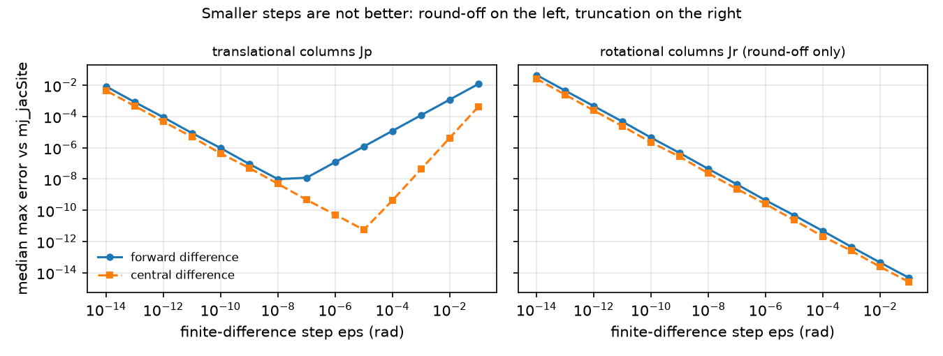
The rotational columns have no truncation error at all: moving one hinge by ε rotates the site by exactly ε about that hinge’s axis, so the difference quotient is exact and only round-off remains (4.8e-15 at ε = 0.1, growing as ε shrinks).
Step 3 · verify τ = Jᵀ F in simulation. Gravity and joint friction loss are switched off so only the external force acts. The arm holds a pose with its position servos (motors that push back toward a commanded angle); a constant force is applied at the gripper site through xfrc_applied (force plus the moment , because xfrc_applied acts at the body’s centre of mass). After 20 s of simulation the joints are at rest (max |q̇| = 8.5e-15 rad/s) and the servo torques are compared with :
| F at site (N) | (N m), joints 1–5 | servo torque (N m), sign flipped | max diff |
|---|---|---|---|
| (0, 0, −2) | 0.0000, 0.4383, 0.5191, 0.2584, 0.0042 | 0.0000, 0.4383, 0.5191, 0.2584, 0.0042 | 4.2e-14 |
| (2, 0, 0) | 0.0052, −0.0395, −0.2569, −0.1872, −0.0036 | same | 7.1e-14 |
| (0, 1.5, 0) | −0.3745, −0.0000, −0.0001, −0.0001, 0.0175 | same | 7.2e-14 |
| (1, −1, 1) | 0.2523, −0.2390, −0.3882, −0.2229, −0.0156 | same | 1.6e-13 |
The servos settle on exactly . A sideways push (0, 1.5, 0) N loads almost only the pan joint; a downward push loads the three pitch joints.
Break it
Section titled “Break it”Push the tip load until a servo saturates. With gravity on, the servos must supply for a downward tip force . Taking the model’s 2.94 N m limit for every joint:
| Pose (rad) | lift axis → tip (m) | gravity torque, lift / elbow (N m) | max extra tip load | limiting joint |
|---|---|---|---|---|
| near (0, −1.5, 1.5, 0.5, 0) | 0.172 | −0.059 / −0.469 | 8.81 N | elbow_flex |
| mid (0, −0.6, 0.9, 0.4, 0) | 0.220 | −0.281 / −0.443 | 9.61 N | elbow_flex |
| stretched (0, 1.3, −1.3, 0, 0) | 0.411 | −0.909 / −0.483 | 4.95 N | shoulder_lift |
Then the stretched case is simulated for 5 s with the force set to a fraction of that limit:
| tip force (N) | × limit | tip drop after 5 s | lift servo torque |
|---|---|---|---|
| 0.00 | 0.0 | 0.5 mm | −0.909 N m |
| 2.48 | 0.5 | 1.2 mm | −1.925 N m |
| 4.46 | 0.9 | 1.8 mm | −2.737 N m |
| 5.45 | 1.1 | 147.4 mm | −2.940 N m |
| 7.43 | 1.5 | 179.7 mm | −2.940 N m |
Below the limit the arm sags by about a millimetre (finite servo stiffness). Ten per cent above it the lift servo clamps at −2.940 N m and the arm falls 147.4 mm. Doubling the lever from 0.220 m to 0.411 m roughly halved the safe load: the Jacobian, not the payload, sets the limit.
On the real robot
Section titled “On the real robot”- The 2.94 N m
forcerangeis a model parameter. The MJCF comment says the position gains and forces were calculated assuming a servo proportional gain of 16; they are “not a 1-to-1 mapping” of LeRobot’s servo gains (so101.xml). Do not read the payload table as a hardware rating. Not yet measured on the real arm. Procedure: hang known weights at the gripper in the stretched pose, record the joint torque (for example from the servo’s current reading, if your driver exposes it), and fit against . - On hardware the static map also carries joint friction (the model’s
frictionloss, switched off in Step 3), gear backlash and cable forces; expect to hold only up to those. - If you compute Jacobians by finite differences anyway (for example around a learned model), use central differences with ε near 1e-5 rad, not 1e-8.
Check yourself
Section titled “Check yourself”Quick check · 2 questions. Click an answer.
1. You compute the position Jacobian by finite differences. Is a smaller step ε always more accurate?
- Yes; the truncation error falls with ε, so the smallest step a double allows is best.
- Yes, but only for central differences.
- No; below the best step round-off takes over, so the error curve is V-shaped.
Why: Step 2 table, the best forward step is 1e-8 (error 9.8e-09) and the best central step 1e-5 (error 5.6e-12); at 1e-14 the central error is 4.5e-03.
2. The model’s servos hold 9.61 N of extra tip load in the mid pose but only 4.95 N in the stretched pose. Why?
- The servo force limit is lower when the arm is stretched.
- The lever from the lift axis to the tip grows from 0.220 to 0.411 m, and scales with that lever.
- The Jacobian is singular in the stretched pose, so no torque reaches the tip.
Why: Break it, every joint has the same 2.94 N m limit; in the stretched pose gravity alone already takes −0.909 N m at the lift and shoulder_lift saturates first.
- Easy. Why is the first entry of exactly 0.0000 for N?
- Medium. Which pose maximizes the shoulder-lift torque per newton of downward tip force? Use the lever column to argue, then check with
mj_jacSite. - Hard. Repeat the ε sweep in float32 (cast positions to
np.float32before differencing). Where do the optimal steps move, and why?
Answers
Section titled “Answers”- Joint 1 (pan) has a vertical axis; a vertical force has no moment about a vertical axis, so .
- The fully stretched horizontal pose: the lift torque per newton equals the horizontal distance from the lift axis to the tip, 0.410 N m/N at the stretched pose in the script output. Check others with the script.
- Not computed here. Expect the minima to move to larger ε, near and with (the float32 machine epsilon).
Takeaways and sources
Section titled “Takeaways and sources”mj_jacSitegives the geometric Jacobian; matched the real site velocity to 7.9e-07 relative error.- Finite differences have an optimal step: 1e-8 (forward, 9.8e-09) and 1e-5 (central, 5.6e-12) in this sweep; smaller is worse.
- held to 1.6e-13 N m in simulation; with a 0.411 m lever the model’s servos hold only 4.95 N of tip load.
Next: lesson 10 · Inverse kinematics and singularities.
Sources
- K. M. Lynch, F. C. Park, Modern Robotics, Ch. 5 “Velocity Kinematics and Statics”. Book page.
- MuJoCo API functions (
mj_jac,mj_jacSite,mju_subQuat). - SO-101 model and servo parameters: MuJoCo Menagerie
robotstudio_so101.